Mitsubishi Grandis. Manual - part 337
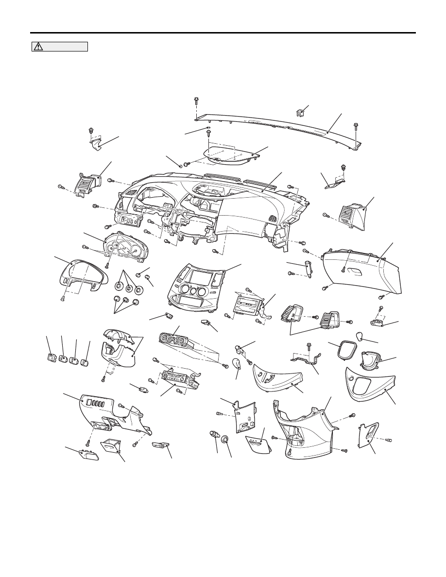
INSTRUMENT PANEL ASSEMBLY
INTERIOR
52A-4
CAUTION
• Refer to GROUP 52B-SRS Service Precautions
and Driver’s, Front Passenger’s Air bag
Module(s) and Clock Spring
before removing the passenger side air bag module.
• Do not subject the SRS-ECU to any shocks when removing or installing the instrument panel.
AC311706
1
2
3
4
5
6
7
8
9
10
11
12
13
14
15
17
18
19
20
21
22
22
23
24
25
26
27
28
29
30
31
32
33
34
35
36
37
38
39
39
40
41
43
44
45
38
37
6
c
g
g
b
i
c
d
c
c
m
d
d
l
c
c
c
i
c
a
k
k
g
c
i
c
k
k
c
c
k
i
k
c
c
d
j
j
h
h
k
AB
42
i
16
Removal steps
1.
Combination meter bezel
2.
Combination meter assembly
<<A>>
3.
Selector lever knob (A/T)
4.
Gear shift lever knob (M/T)
5.
Bezel <M/T>
<<B>>
6.
Selector lever panel
7.
Shift boot <M/T>
8.
Hazard warning lamp switch
•
Cowl side trim (LH) (Refer to
<<C>>
9.
Glove box assembly
10. Glove box damper
11. Glove box lock
•
Fuel filler lid lock release handle
(Refer to GROUP 42, Fuel Filler Lid
Removal steps (Continued)