Mitsubishi Grandis. Manual - part 325
TROUBLESHOOTING
HEATER, AIR CONDITIONER AND VENTILATION
55-185
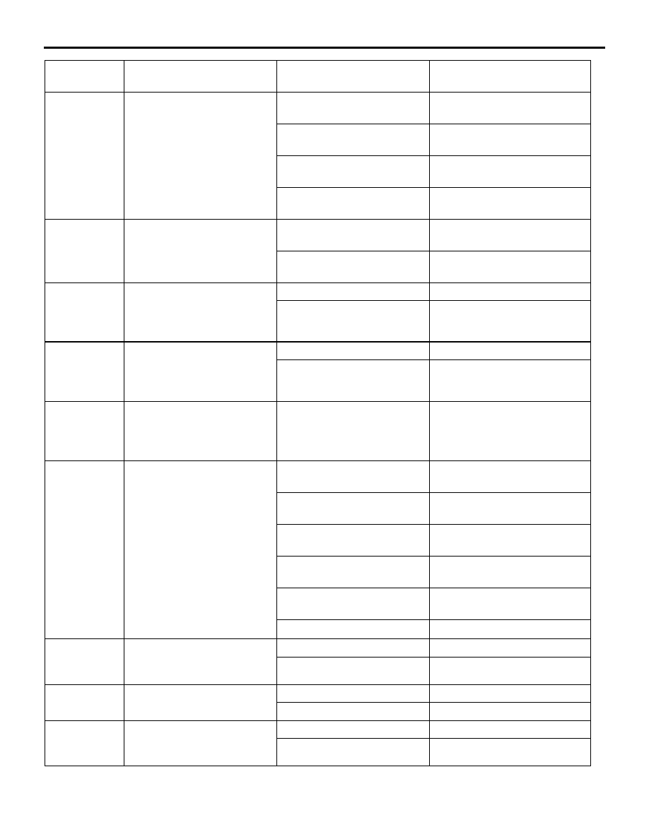
33
Rear control fan OFF
switch<Vehicles with rear
heater, rear cooler or dual
automatic A/C>
Rear air volume adjusting
switch: AUTO
AUTO
Rear air volume adjusting
switch: 1
Lo
Rear air volume adjusting
switch: 2
Me
Rear air volume adjusting
switch: 3
Hi
34
Rear defogger switch
Rear window defogger
switch: ON
ON
Rear window defogger
switch: OFF
OFF
35
PTC heater switch
<Vehicles with rear heater,
rear cooler or dual
automatic A/C>
Heater switch ON
ON
Heater switch OFF
OFF
36
Rear fan SW lamp (Front)
<Vehicles with rear heater,
rear cooler or dual
automatic A/C>
Rear fan switch: ON
ON
Rear fan switch: OFF
OFF
37
Rear control OFF SW lamp
(Front) <Vehicles with rear
heater, rear cooler or dual
automatic A/C>
Rear fan switch: ON
ON
38
Rear control OFF SW lamp
<Vehicles with rear heater,
rear cooler or dual
automatic A/C>
Rear air volume adjusting
switch: OFF
ALL OFF
Rear air volume adjusting
switch: AUTO
AUTO
Rear air volume adjusting
switch: 1
Lo
Rear air volume adjusting
switch: 2
Me
Rear air volume adjusting
switch: 3
Hi
−
ALL ON
39
PTC heater lamp <Vehicles
with rear heater or dual
automatic A/C>
Heater switch ON
ON
Heater switch OFF
OFF
40
Illuminations power supply
Lighting switch: ON
ON
Lighting switch: OFF
OFF
41
PTC heater relay <Vehicles
with rear heater or dual
automatic A/C>
PTC heater relay: ON
ON
PTC heater relay: OFF
OFF
Item No.
Check items
Inspection status
The display contents under
normal conditions