Mitsubishi Grandis. Manual - part 324


  Index      Mitsubishi     Mitsubishi Grandis - service repair manual


Search            


Content   ..  322  323  324  325   ..


Mitsubishi Grandis. Manual - part 324


TROUBLESHOOTING

HEATER, AIR CONDITIONER AND VENTILATION

55-181

Step 5. Check the wiring harness between C-106 
A/C-ECU connector terminal No.5 and the 
ignition switch (ACC).

NOTE: 

Prior to the wiring harness inspection, check joint 
connector C-01 and intermediate connector C-125, 
and repair if necessary.

• Check the A/C-ECU power supply line for open 

circuit.

Q: Is the check result normal?

YES : 

The trouble can be an intermittent 

malfunction (Refer to GROUP 00, How to 
Cope with Intermittent Malfunction 

P.00-5

.)

NO : 

Repair the wiring harness.

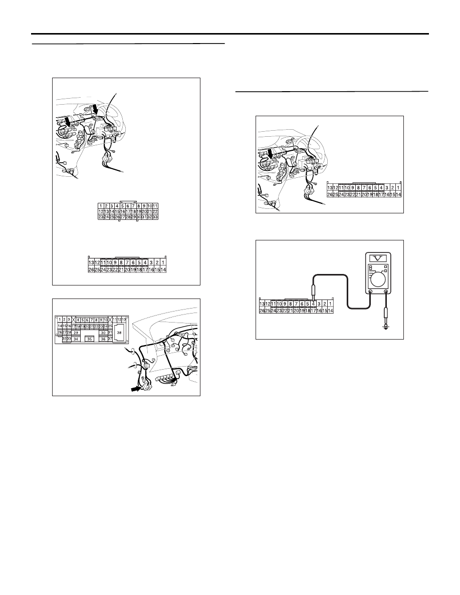
Step 6. Voltage measurement at C-106 A/C-ECU 
connector.

(1) Disconnect the connector, and measure at the 

wiring harness side.

(2) Measure the voltage between terminal 4 and 

body earth.

OK: System voltage

Q: Is the check result normal?

YES : 

Go to Step 8.

NO : 

Go to Step 7.

AC310632AK

Connectors: C-01, C-106 <RHD>

C-01

C-106

C-01

C-106

Harness side

AC310628AB

Connector: C-125 <RHD>

AC310631AB

Connectors: C-106 <RHD>

Harness side

AC310507

Connector C-106 
(Harness side)

BK

TROUBLESHOOTING

HEATER, AIR CONDITIONER AND VENTILATION

55-182

Step 7. Check the wiring harness between C-106 
A/C-ECU connector terminal No.4 and the fusible 
link (26).

NOTE: 

Prior to the wiring harness inspection, check joint 
connector C-31 and intermediate connector C-125, 
and repair if necessary.

• Check the rear fan switch power supply line for 

open circuit.

Q: Is the check result normal?

YES : 

The trouble can be an intermittent 

malfunction (Refer to GROUP 00, How to 
Cope with Intermittent Malfunction 

P.00-5

.)

NO : 

Repair the wiring harness.

Step 8. Resistance measurement at the C-106 
front power transistor connector.

(1) Disconnect the connector, and measure at the 

wiring harness side.

(2) Continuity between terminal 7 and body earth

OK: 2

 or less

Q: Is the check result normal?

YES : 

Replace the A/C-ECU.

NO : 

Go to Step 9.

AC310632 AM

Connectors: C-31, C-106 <RHD>

C-31

C-106

C-31

C-106

Harness side

AC310628AB

Connector: C-125 <RHD>

AC310631AB

Connectors: C-106 <RHD>

Harness side

AC310506

Connector C-106 
(Harness side)

AU

TROUBLESHOOTING

HEATER, AIR CONDITIONER AND VENTILATION

55-183

Step 9. Check the wiring harness between C-106 
A/C-ECU connector terminal No.7 and body 
earth.

NOTE: Prior to the wiring harness inspection, check 
joint connector C-01, and repair if necessary.

• Check the A/C-ECU earth line for open circuit.

Q: Is the check result normal?

YES : 

The trouble can be an intermittent 

malfunction (Refer to GROUP 00, How to 
Cope with Intermittent Malfunction 

P.00-5

.)

NO : 

Repair the wiring harness.

SERVICE DATA REFERENCE TABLE

M1554005100192

AC310614

AG

Connectors: C-01, C-106 <LHD>

C-01

C-106

C-01

C-106

Harness side

Item No.

Check items

Inspection status

The display contents under 
normal conditions

01

Inside temperature sensor

Interior temperature is the 
same as MUT-III displayed 
temperature

02

Outside temperature sensor −

Ambient temperature is the 
same as MUT-III displayed 
temperature

03

Air thermo sensor

Evaporator outlet temperature 
is the same as MUT-III 
displayed temperature

04

Pressure sensor

Refrigerant pressure is the 
same as MUT-III displayed 
pressure.

05

heater water temperature 
sensor

The coolant temperature is 
the same as MUT-III 
displayed temperature

06

Photo sensor

The amount of solar radiation 
is indirectly proportional to 
MUT-III displayed voltage

TROUBLESHOOTING

HEATER, AIR CONDITIONER AND VENTILATION

55-184

10

F.Air mix potentiometer

Front air mix damper 
position: MAX HOT

Approximately 100%

Front air mix damper 
position: MAX COOL

Approximately 0%

11

F.Air mix potentiometer 
(Target)

Display the target value for air 
mix damper

12

R.Air mix potentiometer 
<Vehicles with Dual 
automatic A/C>

Rear air mix damper 
position: MAX HOT

Approximately 100%

Rear air mix damper 
position: MAX COOL

Approximately 0%

13

R.Air mix potentiometer 
(Target) <Vehicles with Dual 
automatic A/C>

Display the target value for air 
mix damper

14

F.Air outlet c/o 
potentiometer

Air outlet changeover 
damper position: FACE

Opening angle: approximately 
100%

Air outlet changeover 
damper position: DEF

Opening angle: approximately 
0%

15

F.Air outlet c/o 
potentiometer (Target)

Display the target value for air 
mix damper

16

In/out air damper motor

Outside/inside air selection 
switch: ON

Inside air

Outside/inside air selection 
switch: OFF

Outside air

20

Front blower fan

Air volume control dial: 
Other than OFF 

Display the rotation speed of 
front blower motor

21

Front blower fan (Target)

Air volume control dial: 
Other than OFF <Vehicles 
with multi-centre display>

Display the target rotation 
speed of front blower motor

22

Rear blower fan <Vehicles 
with rear heater, rear cooler 
or dual automatic A/C>

Rear fan switch: ON

Display the rotation speed of 
rear blower motor

Rear air volume adjusting 
switch: Other than OFF

23

Rear blower fan (Target) 
<Vehicles with rear heater, 
rear cooler or dual 
automatic A/C>

Rear fan switch: ON

Display the target rotation 
speed of rear blower motor

Rear air volume adjusting 
switch: Other than OFF

30

Air conditioner switch

Compressor ON

ON

Compressor OFF

OFF

31

Rear fan SW (Front) 
<Vehicles with rear heater, 
rear cooler or dual 
automatic A/C>

Rear fan switch: ON

ON

Rear fan switch: OFF

OFF

32

Rear control OFF switch 
<Vehicles with rear heater, 
rear cooler or dual 
automatic A/C>

Rear air volume adjusting 
switch: OFF

OFF controlled

Rear air volume adjusting 
switch: Other than OFF

ON controlled

Item No.

Check items

Inspection status

The display contents under 
normal conditions


Content   ..  322  323  324  325   ..