Mitsubishi Grandis. Manual - part 317


  Index      Mitsubishi     Mitsubishi Grandis - service repair manual


Search            


Content   ..  315  316  317  318   ..


Mitsubishi Grandis. Manual - part 317


TROUBLESHOOTING

HEATER, AIR CONDITIONER AND VENTILATION

55-153

Step 1. Connector check: C-215 rear blower 
motor connector

Q: Is the check result normal?

YES : 

Go to Step 2.

NO : 

Repair the connector.

Step 2. Check the rear blower relay

 Refer to 

P.55-196

.

Q: Is the check result normal?

YES : 

Go to Step 3.

NO : 

Replace the rear blower relay.

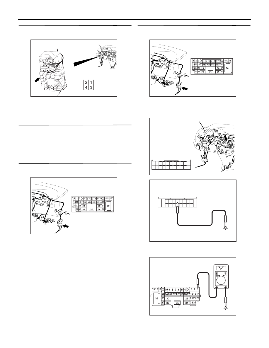
Step 3. Connector check: C-15 intermediate 
connector

Q: Is the check result normal?

YES : 

Go to Step 4.

NO : 

Repair the connector.

Step 4. Voltage measurement at C-15 
intermediate connector.

(1) Disconnect the connector, and measure at the 

wiring harness side.

(2) Turn the ignition switch to the ON position.

(3) Disconnect A/C-ECU connector C-104 and earth 

terminal 56.

(4) Measure the voltage between terminal 1 and 

AC310623

Connector: C-215 <LHD>

AH

Junction block side

Junction block (Front view)

AC310615

AD

Connector: C-15 <LHD>

AC310615

AD

Connector: C-15 <LHD>

AC310613

AK

Connector: C-104 <LHD>

Harness side

51

52

53

54

55

56

57

58

59

60

61

62

63

64

65

66

67

68

69

70

71

72

AC309471

51

52

53

54

55

56

57

58

59

60

61

62

63

64

65

66

67

68

69

70

71

72

AC309471AH

Connector C-104 
(Harness side)

AC310507

Connector C-15 

BE

TROUBLESHOOTING

HEATER, AIR CONDITIONER AND VENTILATION

55-154

body earth.

OK: System voltage

Q: Is the check result normal?

YES : 

Go to Step 11.

NO : 

Go to Step 5.

Step 5. Voltage measurement at C-215 rear 
blower relay connector.

(1) Remove the relay, and measure at the relay block 

side.

(2) Turn the ignition switch to the "ON" position.

(3) Voltage between terminal 3 and body earth.

OK: System voltage

Q: Is the check result normal?

YES : 

 Go to Step 7.

NO : 

 Go to Step 6.

Step 6. Check the wiring harness between C-215 
rear blower relay connector terminal No.3 and 
the ignition switch (IG2).

NOTE: 

Prior to the wiring harness inspection, check junction 
block connectors C-202, C-205 and joint connector 
C-31, and repair if necessary.

• Check the rear blower relay power supply line for 

open circuit.

Q: Is the check result normal?

YES : 

The trouble can be an intermittent 

malfunction (Refer to GROUP 00, How to 
Cope with Intermittent Malfunction 

P.00-5

).

NO : 

Repair the wiring harness.

AC310623

Connector: C-215 <LHD>

AH

Junction block side

Junction block (Front view)

AC310507BF

Connector C-215 
(Junction block side)

AC310624

Connectors: C-202, C-205, C-215 <LHD>

AN

Junction block (Front view)

C-205

C-202

C-205

Harness side

C-202

Harness side

C-215

Junction block side

C-215

AC310613

AP

Connector: C-31 <LHD>

TROUBLESHOOTING

HEATER, AIR CONDITIONER AND VENTILATION

55-155

Step 7. Voltage measurement at C-215 rear 
blower relay connector.

(1) Remove the relay, and measure at the relay block 

side.

(2) Turn the ignition switch to the "ON" position.

(3) Voltage between terminal 4 and body earth.

OK: System voltage

Q: Is the check result normal?

YES : 

 Go to Step 9.

NO : 

 Go to Step 8.

Step 8. Check the wiring harness between C-215 
rear blower relay connector terminal No.4 and 
the fusible link (30).

NOTE: 

Prior to the wiring harness inspection, check 
intermediate connector C-125 and junction block 
connector C-201, and repair if necessary.

• Check the rear blower relay power supply line for 

open circuit.

Q: Is the check result normal?

YES : 

The trouble can be an intermittent 

malfunction (Refer to GROUP 00, How to 
Cope with Intermittent Malfunction 

P.00-5

).

NO : 

Repair the wiring harness.

AC310623

Connector: C-215 <LHD>

AH

Junction block side

Junction block (Front view)

AC310507

Connector C-215 
(Junction block side)

BG

AC310624

Connectors: C-201, C-215 <LHD>

AO

Junction block (Front view)

C-215

Harness side

C-201

C-201

Junction block side

C-215

AC310613

AD

Connector: C-125 <LHD>

TROUBLESHOOTING

HEATER, AIR CONDITIONER AND VENTILATION

55-156

Step 9. Check the wiring harness between C-215 
rear blower relay connector terminal No.2 and 
C-104 A/C-ECU connector terminal No.56.

NOTE: Prior to the wiring harness inspection, check 
junction block connector C-201, and repair if 
necessary.

• Check the rear blower relay power supply line for 

open circuit.

Q: Is the check result normal?

YES : 

 Go to Step 10.

NO : 

Repair the wiring harness.

Step 10. Check the wiring harness between C-215 
rear blower relay connector terminal No.4 and 
C-15 intermediate connector terminal No.1.

NOTE: Prior to the wiring harness inspection, check 
junction block connector C-201, and repair if 
necessary.

• Check the rear blower relay power supply line for 

open circuit.

Q: Is the check result normal?

YES : 

The trouble can be an intermittent 

malfunction (Refer to GROUP 00, How to 
Cope with Intermittent Malfunction 

P.00-5

).

NO : 

Repair the wiring harness.

AC310613

AK

Connector: C-104 <LHD>

Harness side

51

52

53

54

55

56

57

58

59

60

61

62

63

64

65

66

67

68

69

70

71

72

AC310624

Connectors: C-201, C-215 <LHD>

AO

Junction block (Front view)

C-215

Harness side

C-201

C-201

Junction block side

C-215

AC310615

AD

Connector: C-15 <LHD>

AC310624

Connectors: C-201, C-215 <LHD>

AO

Junction block (Front view)

C-215

Harness side

C-201

C-201

Junction block side

C-215


Content   ..  315  316  317  318   ..