Mitsubishi Grandis. Manual - part 268


  Index      Mitsubishi     Mitsubishi Grandis - service repair manual


Search            


Content   ..  266  267  268  269   ..


Mitsubishi Grandis. Manual - part 268


INPUT SIGNAL PROCEDURES

SMART WIRING SYSTEM (SWS) USING SWS MONITOR

54C-534

Step 2. Check the tailgate lock release handle.

Refer to GROUP 42 

− Tailgate 

P.42-51

.

Q: Is the check result normal?

YES : 

Go to Step 3

NO : 

Replace the tailgate lock release handle.

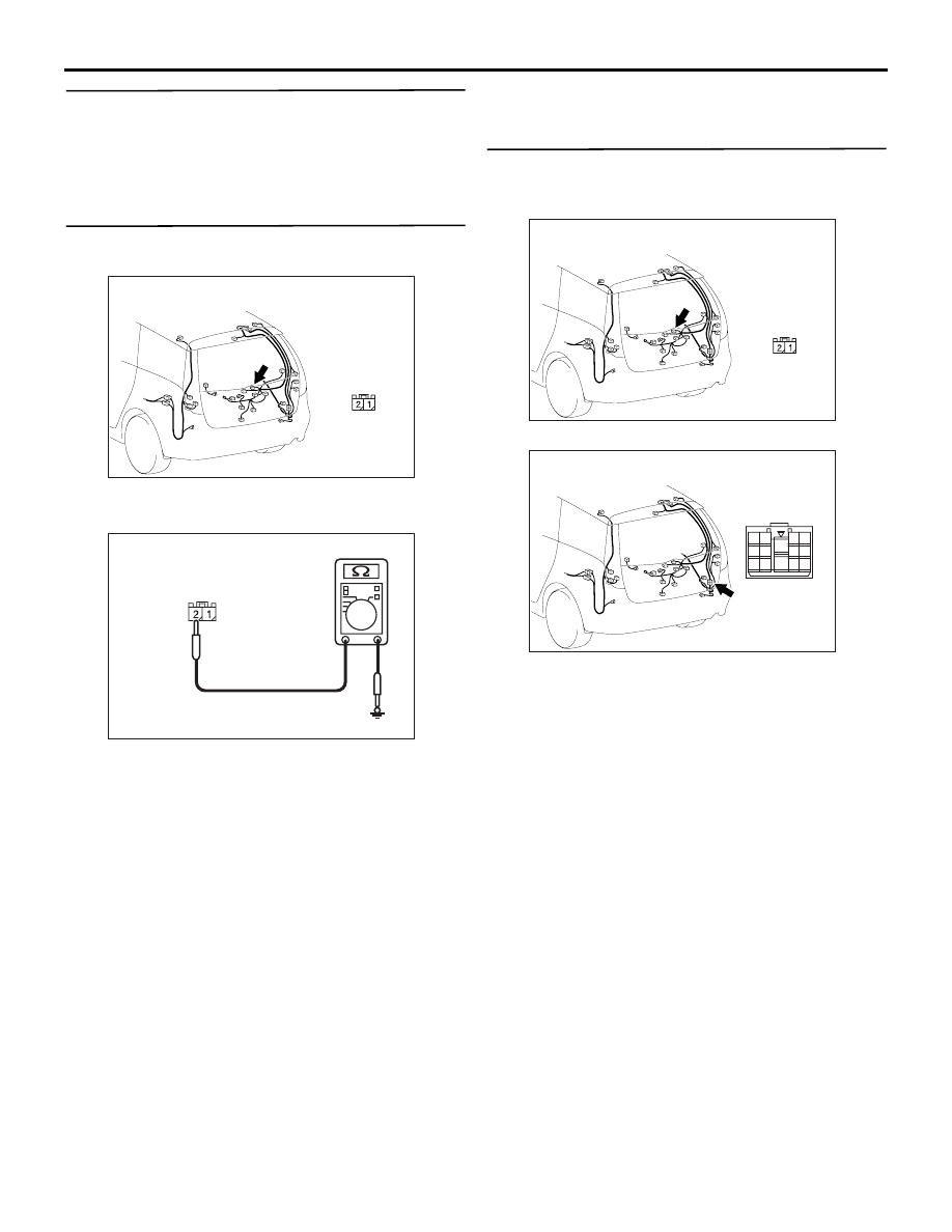
Step 3. Resistance measurement at the G-06 
tailgate lock release handle connector

(1) Disconnect the connector, and measure at the 

wiring harness side.

(2) Resistance between G-06 tailgate lock release 

handle connector terminal No.2 and body earth

OK: 2 

 or less

Q: Is the check result normal?

YES : 

Go to Step 5.

NO : 

Go to Step 4.

Step 4. Check the wiring harness between G-06 
tailgate lock release handle connector terminal 
No.2 and body earth

NOTE: 

Prior to the wiring harness inspection, check 
intermediate connector G-14, and repair if 
necessary.

• Check the earth wires for open circuit.

Q: Is the check result normal?

YES : 

The trouble can be an intermittent 

malfunction (Refer to GROUP 00 

− How to 

Cope with Intermittent Malfunction 

P.00-5

).

NO : 

Repair the wiring harness.

AC312078

Connector: G-06

AE

Harness side

AC312730

Harness side

AL

AC312078

Connector: G-06

AE

Harness side

AC312078

Connector: G-14

AC

2

1

4

3

13

8

11

10

5

7

12

6

14

9

INPUT SIGNAL PROCEDURES

SMART WIRING SYSTEM (SWS) USING SWS MONITOR

54C-535

Step 5. Connector check: C-221 ETACS-ECU 
connector

Q: Is the check result normal?

YES : 

Go to Step 6.

NO : 

Repair the defective connector.

AC312037

Connector: C-221  <LHD>

Junction block (Rear view)

AD

Harness side

AC312047

Connector: C-221  <RHD>

Junction block (Rear view)

AD

Harness side

INPUT SIGNAL PROCEDURES

SMART WIRING SYSTEM (SWS) USING SWS MONITOR

54C-536

Step 6. Check the wiring harness from G-06 
tailgate lock release handle connector terminal 
No.1 to C-221 ETACS-ECU connector terminal 
No.62.

NOTE: 

Prior to the wiring harness inspection, check 
intermediate connector C-16, G-14 and repair if 
necessary.

• Check the input line for open circuit.

Q: Is the check result normal?

YES : 

Go to Step 7.

NO : 

Repair the wiring harness.

Step 7. ETACS switch data by using the SWS 
monitor

Check the input signal from the Tailgate lock release 
handle.

• Tailgate lock release handle: from OFF to ON

OK: Normal condition is displayed.

Q: Is the check result normal?

AC312078

Connector: G-06

AE

Harness side

AC312037

Connector: C-221  <LHD>

Junction block (Rear view)

AD

Harness side

AC312047

Connector: C-221  <RHD>

Junction block (Rear view)

AD

Harness side

Item No.

Item name

Normal conditions

Item 30

GTE OPENER 
SW

OFF to ON (only 
when switch is 
operated)

AC312033

Connector: C-16 <LHD>

AB

9

21

33

35

24

12

3 4

7

8

5 6

39

28

41

30

18

4243

31

1920

32

40

29

1617

38

27

15

37

36

26

14

13

25

2

1

34

23

11

10

22

AC312043

Connector: C-16 <RHD>

AH

9

21

33

35

24

12

3 4

7

8

5 6

39

28

41

30

18

4243

31

1920

32

40

29

1617

38

27

15

37

36

26

14

13

25

2

1

34

23

11

10

22

AC312078

Connector: G-14

AC

2

1

4

3

13

8

11

10

5

7

12

6

14

9

INPUT SIGNAL PROCEDURES

SMART WIRING SYSTEM (SWS) USING SWS MONITOR

54C-537

YES : 

The trouble can be an intermittent 

malfunction (Refer to GROUP 00 

− How to 

Cope with Intermittent Malfunction 

P.00-5

).

NO : 

Replace the ETACS-ECU.

Inspection Procedure Q-19: The driver's seat belt switch signal is not received. <LH drive vehicles>

CAUTION

Whenever the ECU is replaced, ensure that the 
input signal circuit is normal.

COMMENTS ON TROUBLE SYMPTOM

Input signal from the driver's seat belt switch signal is 
used to operate the central door locking function. If 
the signal is abnormal, the central door locking 
function will not work normally.

POSSIBLE CAUSES

• Malfunction of the driver's seat belt switch

• Malfunction of the ETACS-ECU

• Malfunction of the combination meter

• Damaged harness wires and connectors

DIAGNOSTIC PROCEDURE

Step 1. MUT-III CAN bus diagnostics

Use the MUT-III to diagnose the CAN bus lines.

Q: Is the check result normal?

YES : 

Go to Step 2.

NO : 

Repair the CAN bus line (Refer to GROUP 
54D 

− Diagnosis 

P.54D-16

).

Step 2. MUT-III diagnosis code

Check whether the combination meter-related 
diagnosis code is set.

Q: Is the diagnosis code set?

COMBINATION METER

SEAT BELT
SWITCH (LH)

Wire colour code
B : Black     LG : Light green
G : Green     L : Blue
W : White     Y : Yellow
SB : Sky blue     BR : Brown
O : Orange     GR : Gray
R : Red     P : Pink     V : Violet

Driver's Seat Belt Switch Input Circuit <LHD>

ETACS-ECU

CAN COMMUNICATION LINE
(CAN_L LINE)

CAN COMMUNICATION LINE
(CAN_H LINE)


Content   ..  266  267  268  269   ..