Mitsubishi Grandis. Manual - part 264


  Index      Mitsubishi     Mitsubishi Grandis - service repair manual


Search            


Content   ..  262  263  264  265   ..


Mitsubishi Grandis. Manual - part 264


INPUT SIGNAL PROCEDURES

SMART WIRING SYSTEM (SWS) USING SWS MONITOR

54C-518

Inspection Procedure Q-15: The driver's door lock actuator switch signal is not received. <RH drive 
vehicles>

CAUTION

Whenever the ECU is replaced, ensure that the 
input signal circuit is normal.

COMMENTS ON TROUBLE SYMPTOM

Input signal from the driver's door lock actuator is 
used to operate the functions below. If the signal is 
abnormal, these functions will not work normally.

• Central door locking

• Interior lamps

POSSIBLE CAUSES

• Malfunction of the front door lock actuator (RH)

• Malfunction of the ETACS-ECU

• Damaged harness wires and connectors
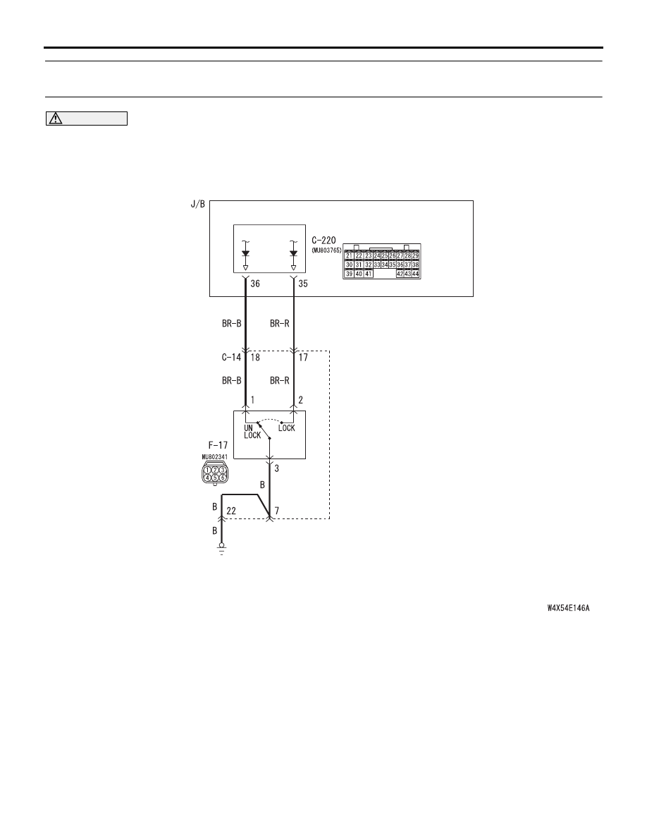
ETACS-ECU

DOOR LOCK
ACTUATOR
(FRONT: RH)

Wire colour code
B : Black     LG : Light green     G : Green     L : Blue     W : White     Y : Yellow     SB : Sky blue
BR : Brown     O : Orange     GR : Gray     R : Red     P : Pink     V : Violet

Door Lock Actuator Input Circuit <RHD>

INPUT SIGNAL PROCEDURES

SMART WIRING SYSTEM (SWS) USING SWS MONITOR

54C-519

DIAGNOSIS PROCEDURE

Step 1. Connector check: F-17 front door lock 
actuator (RH) connector

Q: Is the check result normal?

YES : 

Go to Step 2.

NO : 

Repair the defective connector.

Step 2. Check the front door lock actuator (RH).

Refer to GROUP 42 

− Door 

P.42-38

.

Q: Is the check result normal?

YES : 

Go to Step 3.

NO : 

Replace the front door lock actuator (RH).

Step 3. Resistance measurement at the F-17 front 
door lock actuator (RH) connector

(1) Disconnect the connector, and measure at the 

wiring harness side.

(2) Resistance between F-17 front door lock actuator 

(RH) connector terminal No.3 and body earth

OK: 2 

 or less

Q: Is the check result normal?

YES : 

Go to Step 5.

NO : 

Go to Step 4.

Step 4. Check the wiring harness between F-17 
front door lock actuator (RH) connector terminal 
No.3 and body earth

NOTE: 

Prior to the wiring harness inspection, check 
intermediate connector C-14, and repair if necessary.

• Check the earth wires for open circuit.

Q: Is the check result normal?

YES : 

The trouble can be an intermittent 

malfunction (Refer to GROUP 00 

− How to 

Cope with Intermittent Malfunction 

P.00-5

).

NO : 

Repair the wiring harness.

AC312089

AB

Connector: F-17

Harness side

5

6

4

2

3

1

<RHD>

AC312089

AB

Connector: F-17

Harness side

5

6

4

2

3

1

<RHD>

AC312730AG

Connector F-17
(Harness side)

5

6

4

2

3

1

AC312089

AB

Connector: F-17

Harness side

5

6

4

2

3

1

<RHD>

AC312043

Connector: C-14 <RHD>

AG

INPUT SIGNAL PROCEDURES

SMART WIRING SYSTEM (SWS) USING SWS MONITOR

54C-520

Step 5. Connector check: C-220 ETACS-ECU 
connector

Q: Is the check result normal?

YES : 

Go to Step 6.

NO : 

Repair the defective connector.

Step 6. Check the wiring harness from F-17 front 
door lock actuator (RH) connector terminal Nos.1 
and 2 to C-220 ETACS-ECU connector terminal 
Nos.35 and 36.

NOTE: 

Prior to the wiring harness inspection, check 
intermediate connector C-14, and repair if necessary.

• Check the input line for open circuit.

Q: Is the check result normal?

YES : 

Go to Step 7.

NO : 

Repair the wiring harness.

AC312047

Connector: C-220

Junction block (Rear view)

AC

<RHD>

Harness side

AC312089

AB

Connector: F-17

Harness side

5

6

4

2

3

1

<RHD>

AC312047

Connector: C-220

Junction block (Rear view)

AC

<RHD>

Harness side

AC312043

Connector: C-14 <RHD>

AG

INPUT SIGNAL PROCEDURES

SMART WIRING SYSTEM (SWS) USING SWS MONITOR

54C-521

Step 7. ETACS switch data by using the SWS 
monitor

Check the input signal from the driver's door lock 
actuator switch.

• Driver's door lock actuator switch: LOCK → 

UNLOCK

OK: Normal conditions are displayed for all 
the items.

Q: Is the check result normal?

YES : 

The trouble can be an intermittent 

malfunction (Refer to GROUP 00 

− How to 

Cope with Intermittent Malfunction 

P.00-5

).

NO : 

Replace the ETACS-ECU.

Inspection Procedure Q-16: The passenger’s door lock key switch signal is not detected. <LH drive 
vehicles>

CAUTION

Whenever the ECU is replaced, ensure that the 
input signal circuit is normal.

COMMENTS ON TROUBLE SYMPTOM

Input signal from the front passenger's door lock key 
switch is used to operate the central door locking 
function. If the signal is abnormal, the central door 

locking function will not work normally.

Item No. Item name

Normal 
conditions

Item 21

DR DOR LCK SW

ON 

→ OFF

Item 22

DR DOR ULK SW

OFF 

→ ON

Door Lock Key Cylinder Switch Input Circuit <LHD>

DOOR KEY
SWITCH

ETACS-ECU

Wire colour code
B : Black     LG : Light green     G : Green     L : Blue     W : White     Y : Yellow     SB : Sky blue
BR : Brown     O : Orange     GR : Gray     R : Red     P : Pink     V : Violet


Content   ..  262  263  264  265   ..