Mitsubishi Grandis. Manual - part 261


  Index      Mitsubishi     Mitsubishi Grandis - service repair manual


Search            


Content   ..  259  260  261  262   ..


Mitsubishi Grandis. Manual - part 261


INPUT SIGNAL PROCEDURES

SMART WIRING SYSTEM (SWS) USING SWS MONITOR

54C-506

COMMENTS ON TROUBLE SYMPTOM

Input signals from all the door switches are used to 
operate the functions below. If the signal(s) are 
abnormal, these functions will not work normally.

• Door-ajar warning buzzer

• Keyless entry system

• Interior lamps

• Interior lamp automatic-shutdown

• Door-ajar warning lamp

POSSIBLE CAUSES

• Malfunction of the door switches

• Malfunction of the ETACS-ECU

• Damaged harness wires and connectors

DIAGNOSIS PROCEDURE

Step 1. SWS monitor data list
<Selected item> ETACS ECU

• Driver's door is open

OK: Normal condition is displayed.

Q: Is the check result normal?

YES : 

Go to Step 2.

NO : 

Refer to inspection procedure Q-5 "The 
driver's door switch signal is not received 
<LH drive vehicles>

P.54C-474

  or <RH 

drive vehicles>

P.54C-476

 ."

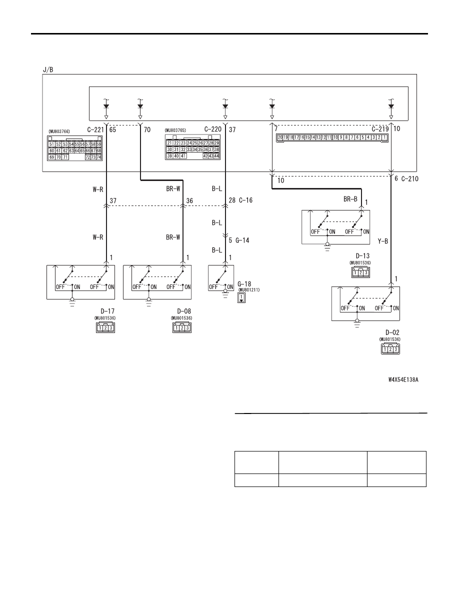
Door Switches Input Circuit <RHD>

DOOR 
SWITCH 
(FRONT: LH)

DOOR 
SWITCH 
(REAR: RH)

DOOR 
SWITCH 
(FRONT: RH)

DOOR 
SWITCH 
(REAR: LH)

ETACS-ECU

Wire colour code
B : Black     LG : Light green     G : Green     L : Blue     W : White     Y : Yellow     SB : Sky blue
BR : Brown     O : Orange     GR : Gray     R : Red     P : Pink     V : Violet

J/B SIDE

TAILGATE
SWITCH

Item No.

Item name

Normal 
condition

Item 32

DR DOOR SW

ON

INPUT SIGNAL PROCEDURES

SMART WIRING SYSTEM (SWS) USING SWS MONITOR

54C-507

Step 2. Connector check: D-17 (front: LH), D-02 
(front: RH), D-08 (rear: RH) or D-13 (rear: LH) 
door switch connectors or G-18 tailgate switch 
connector, and C-219, C-220 and C-221 
ETACS-ECU connector

INPUT SIGNAL PROCEDURES

SMART WIRING SYSTEM (SWS) USING SWS MONITOR

54C-508

AC312054

Connectors: D-13, D-17

D-13

AB

D-17

Harness side

D-17

D-13

<LHD>

AC312054

Connectors: D-13, D-17

D-13

AC

D-17

Harness side

D-17

D-13

<RHD>

AC312052

Connectors: D-02, D-08

D-02

AB

D-08

<LHD>

D-02

D-08

Harness side

AC312059

Connectors: D-02, D-08

D-02

AB

D-02

D-08

D-08

Harness side

<RHD>

INPUT SIGNAL PROCEDURES

SMART WIRING SYSTEM (SWS) USING SWS MONITOR

54C-509

Q: Is the check result normal?

YES : 

Go to Step 3.

NO : 

Repair the defective connector.

Step 3. Check the installation condition.

Check that the door switch is installed on the body 
correctly.

Q: Is the check result normal?

YES : 

Go to Step 4.

NO : 

Correct the installation condition.

Step 4. Check the door switch.

Refer to GROUP 42 

− Door 

P.42-32

.

Q: Is the check result normal?

YES : 

Go to Step 5.

NO : 

Replace the door switch.

AC312078

Connector: G-18

AB

Harness side

AC312038

Connectors: C-219, C-220, C-221

C-220

AB

C-221

C-219

Junction block side

28

37

43

29

44

38

23

32

41

2425 26 27

34

42

36

35

33

21 22

30

39 40

31

Junction block side

Junction block side

68

74

63

66

7273

67

65

64

61

70 71

62

69

60

5758 59

56

55

52

54

53

51

C-220

C-219

C-221

1

2

3

4

5

6

7

8

9

10

11

12

13

14

17

18

19

20

15

16

<LHD>

AC312048

Connectors: C-219, C-220, C-221

C-220

AB

C-221

C-219

Junction block side

28

37

43

29

44

38

23

32

41

2425 26 27

34

42

36

35

33

21 22

30

39 40

31

Junction block side

Junction block side

68

74

63

66

7273

67

65

64

61

70 71

62

69

60

5758 59

56

55

52

54

53

51

C-220

C-219

C-221

1

2

3

4

5

6

7

8

9

10

11

12

13

14

17

18

19

20

15

16

<RHD>


Content   ..  259  260  261  262   ..