Mitsubishi Grandis. Manual - part 259


  Index      Mitsubishi     Mitsubishi Grandis - service repair manual


Search            


Content   ..  257  258  259  260   ..


Mitsubishi Grandis. Manual - part 259


INPUT SIGNAL PROCEDURES

SMART WIRING SYSTEM (SWS) USING SWS MONITOR

54C-498

COMMENTS ON TROUBLE SYMPTOM

Input signal from the hazard warning lamp switch is 
used to operate the functions below. If the signal is 
abnormal, these functions will not work normally.

• Turn-signal lamp operation sound

• Keyless entry system (encrypted code 

registration)

• Keyless entry hazard answerback

• Hazard warning lamp

POSSIBLE CAUSES

• Malfunction of the hazard warning lamp switch

• Malfunction of the ETACS-ECU

• Damaged harness wires and connectors

DIAGNOSIS PROCEDURE

Step 1. Connector check: C-123 hazard warning 
lamp switch connector

Q: Is the check result normal?

YES : 

Go to Step 2.

NO : 

Repair the defective connector.

ETACS-
ECU

HAZARD
WARNING
LAMP SWITCH

Wire colour code
B : Black     LG : Light green     G : Green     L : Blue     W : White     Y : Yellow     SB : Sky blue
BR : Brown     O : Orange     GR : Gray     R : Red     P : Pink     V : Violet

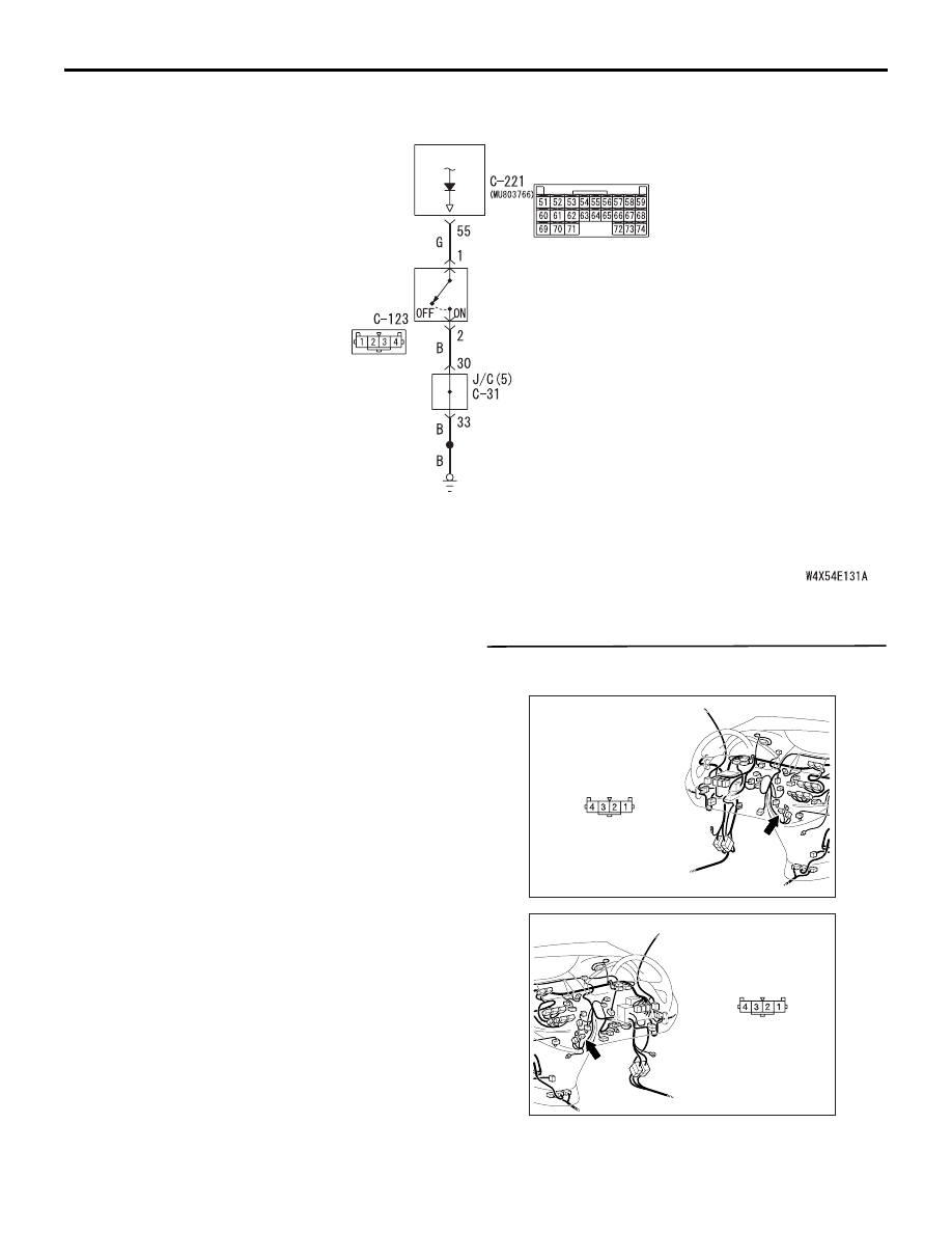
Hazard Warning Lamp Switch Input Circuit <RHD>

AC312031

AD

Connector: C-123 <LHD>

Harness side

AC312043AD

Connector: C-123 <RHD>

Harness side

INPUT SIGNAL PROCEDURES

SMART WIRING SYSTEM (SWS) USING SWS MONITOR

54C-499

Step 2. Check the hazard warning lamp switch.
Refer to GROUP 54A 

− Hazard warning lamp switch 

P.54A-101

.

Q: Is the check result normal?

YES : 

Go to Step 3.

NO : 

Replace the hazard warning lamp switch.

Step 3. Resistance measurement at the C-123 
hazard warning lamp switch connector.

(1) Disconnect the connector, and measure at the 

wiring harness side.

(2) Resistance between C-123 hazard warning lamp 

switch connector terminal No.2 and body earth

OK: 2 

 or less

Q: Is the check result normal?

YES : 

Go to Step 5.

NO : 

Go to Step 4.

Step 4. Check the wiring harness between C-123 
hazard warning lamp switch connector terminal 
No.2 and the body earth.

NOTE: 

Prior to the wiring harness inspection, check joint 
connector C-31 <RH drive vehicles>, and repair if 
necessary.

• Check the earth wires for open circuit.

Q: Is the check result normal?

YES : 

The trouble can be an intermittent 

malfunction (Refer to GROUP 00 

− How to 

Cope with Intermittent Malfunction 

P.00-5

).

NO : 

Repair the wiring harness.

AC312031

AD

Connector: C-123 <LHD>

Harness side

AC312043AD

Connector: C-123 <RHD>

Harness side

AC312730AD

Connector C-123
(Harness side)

AC312031

AD

Connector: C-123 <LHD>

Harness side

AC312043AD

Connector: C-123 <RHD>

Harness side

AC312043AE

Connector: C-31 <RHD>

INPUT SIGNAL PROCEDURES

SMART WIRING SYSTEM (SWS) USING SWS MONITOR

54C-500

Step 5. Connector check: C-221 ETACS-ECU 
connector

Q: Is the check result normal?

YES : 

Go to Step 6.

NO : 

Repair the defective connector.

Step 6. Check the wiring harness between C-221 
ETACS-ECU connector terminal No.55 and C-123 
hazard warning lamp switch connector terminal 
No.1.

• Check the input line for open circuit.

Q: Is the check result normal?

YES : 

Go to Step 7.

NO : 

Repair the wiring harness.

AC312037

Connector: C-221  <LHD>

Junction block (Rear view)

AD

Harness side

AC312047

Connector: C-221  <RHD>

Junction block (Rear view)

AD

Harness side

AC312031

AD

Connector: C-123 <LHD>

Harness side

AC312043AD

Connector: C-123 <RHD>

Harness side

AC312037

Connector: C-221  <LHD>

Junction block (Rear view)

AD

Harness side

AC312047

Connector: C-221  <RHD>

Junction block (Rear view)

AD

Harness side

INPUT SIGNAL PROCEDURES

SMART WIRING SYSTEM (SWS) USING SWS MONITOR

54C-501

Step 7. ETACS switch data by using the SWS 
monitor

Check the input signal from the hazard warning lamp 
switch.

• hazard warning lamp switch: from OFF to ON

OK: Normal condition is displayed.

Q: Is the check result normal?

YES : 

The trouble can be an intermittent 

malfunction (Refer to GROUP 00 

− How to 

Cope with Intermittent Malfunction 

P.00-5

).

NO : 

Replace the ETACS-ECU.

Inspection Procedure Q-13: The rear fog lamp switch signal is not received.

CAUTION

Whenever the ECU is replaced, ensure that the 
input signal circuit is normal.

Item No.

Item name

Normal condition

Item 04

HAZARD LMP 
SW

OFF to ON (only 
when switch is 
operated)

Rear Fog Lamp Switch Input Circuit

ETACS-
ECU

FOG LAMP
SWITCH

Wire colour code
B : Black     LG : Light green     G : Green     L : Blue     W : White     Y : Yellow     SB : Sky blue
BR : Brown     O : Orange     GR : Gray     R : Red     P : Pink     V : Violet

<RHD>

<LHD>


Content   ..  257  258  259  260   ..