Mitsubishi Grandis. Manual - part 257
INPUT SIGNAL PROCEDURES
SMART WIRING SYSTEM (SWS) USING SWS MONITOR
54C-490
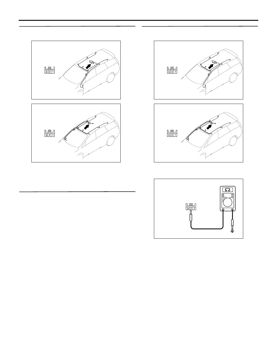
Step 2. Connector check: E-05 sunroof switch
connector
Q: Is the check result normal?
YES :
Go to Step 3.
NO :
Repair the defective connector.
Step 3. Check the sunroof switch.
Refer to GROUP 42
− Sunroof
.
Q: Is the check result normal?
YES :
Go to Step 4.
NO :
Replace the sunroof switch.
Step 4. Resistance measurement at the E-05
sunroof switch connector.
(1) Disconnect the connector, and measure at the
wiring harness side.
(2) Continuity between E-05 sunroof switch
connector terminal No.2 and body earth
OK: 2
Ω or less
Q: Is the check result normal?
YES :
Go to Step 6.
NO :
Go to Step 5.
AC312062
AB
Harness side
Connector: E-05 <LHD>
AC312067
AB
Harness side
Connector: E-05 <RHD>
AC312062
AB
Harness side
Connector: E-05 <LHD>
AC312067
AB
Harness side
Connector: E-05 <RHD>
AC312730AN
Connector E-05
(Harness side)