Mitsubishi Grandis. Manual - part 227


  Index      Mitsubishi     Mitsubishi Grandis - service repair manual


Search            


Content   ..  225  226  227  228   ..


Mitsubishi Grandis. Manual - part 227


SYMPTOM PROCEDURES

SMART WIRING SYSTEM (SWS) USING SWS MONITOR

54C-370

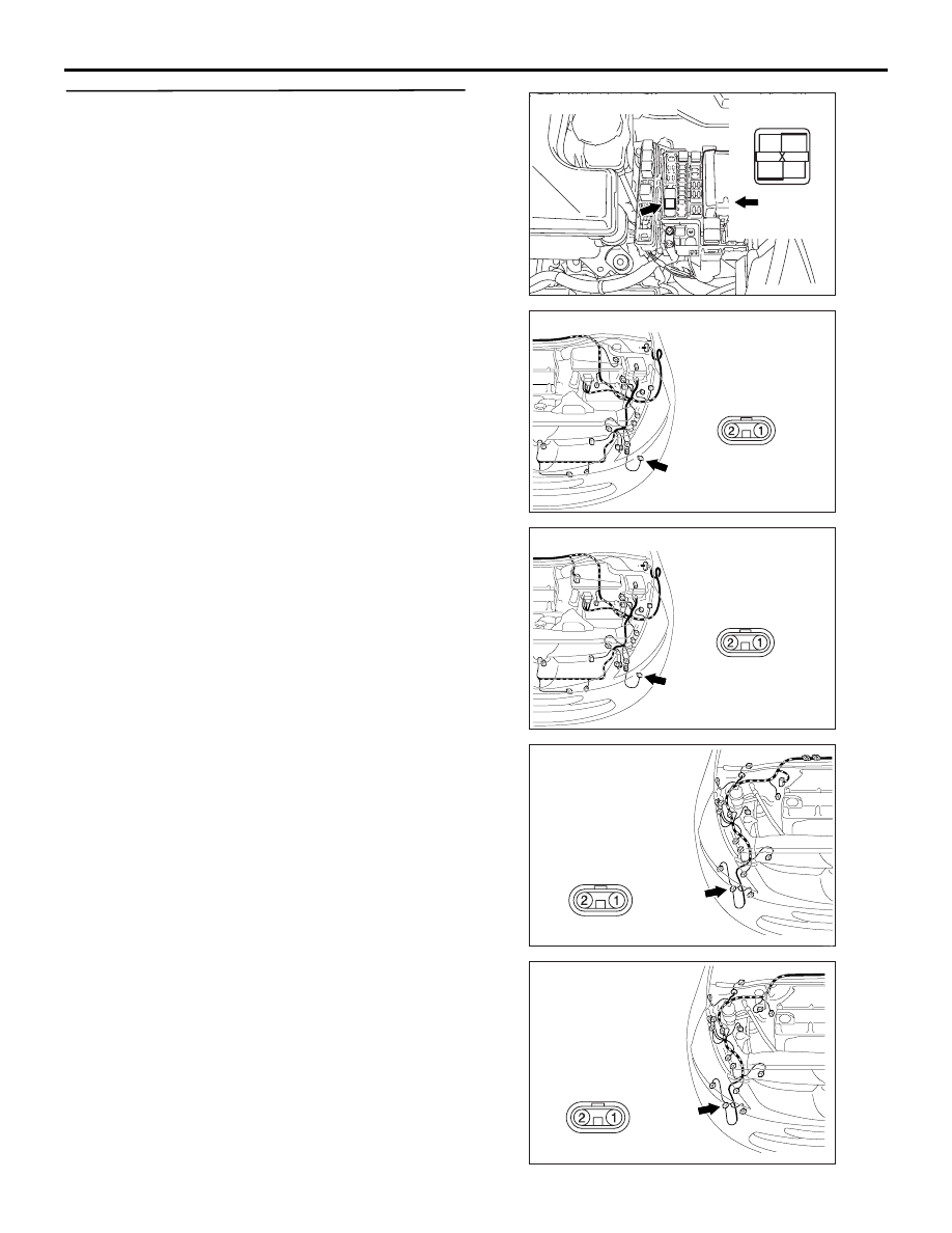
Step 7. Check the wiring harness from A-32 front 
fog lamp (RH) connector or A-24 front fog lamp 
(LH) connector terminal No.2 to A-08X front fog 
lamp relay connector terminal No.4.

AC311521AD

Connector: A-08X

1

3

2

4

Front of 
vehicle

Relay box side

AC310403

A-24 (B)

AG

Connector: A-24 <LHD>

Harness side

AC310398

A-24 (B)

AG

Connector: A-24 <RHD>

Harness side

AC310401

Connector: A-32 <LHD>

Harness side

A-32 (B)

AC

AC310396

Connector: A-32 <RHD>

Harness side

A-32 (B)

AC

SYMPTOM PROCEDURES

SMART WIRING SYSTEM (SWS) USING SWS MONITOR

54C-371

• Check the power supply line for open circuit.

Q: Is the check result normal?

YES : 

Go to Step 8.

NO : 

Repair the wiring harness.

Step 8. Retest the system.

Check that the front fog lamp illuminate normally.

Q: Is the check result normal?

YES : 

The trouble can be an intermittent 

malfunction (Refer to GROUP 00 

− How to 

Cope with Intermittent Malfunction 

P.00-5

).

NO : 

Replace the front fog lamp(s).

Inspection Procedure O-4: The front fog lamp indicator does not illuminate normally.

CAUTION

Whenever the ECU is replaced, ensure that the 
input and output signal circuits are normal.

COMMENTS ON TROUBLE SYMPTOM

If the front fog lamp indicator does not illuminate 
normally, connector(s), wiring harness in the CAN 
bus lines, the ETACS-ECU or the combination meter 
may be defective.

POSSIBLE CAUSES

• The combination meter may be defective

• The ETACS-ECU may be defective

• Damaged harness wires and connectors

DIAGNOSIS PROCEDURE

Step 1. Check the front fog lamps.

When the front fog lamp switch is operated, check 
that the front fog lamps illuminate/go off normally.

Q: Is the check result normal?

YES : 

Go to Step 2.

NO : 

Refer to Inspection Procedure O-3 "Any of 
the front fog lamps does not illuminate 

P.54C-365

."

Step 2. MUT-III CAN bus diagnostics.

Use the MUT-III to diagnose the CAN bus lines.

Q: Is the check result normal?

YES : 

Go to Step 3.

NO : 

Repair the CAN bus line (Refer to GROUP 
54D, Diagnosis 

P.54D-16

).

Step 3. Check for combination meter diagnosis 
code.

Check whether the combination meter-related 
diagnosis code is set.

Q: Is the diagnosis code set?

YES : 

Diagnose the combination meter (Refer to 

GROUP 54A 

− Troubleshooting 

P.54A-35

).

NO : 

Go to Step 4.

INPUT SIGNAL

ETACS-ECU

COMBINATION
METER

CAN COMMUNICATION LINE
(CAN_L LINE)

CAN COMMUNICATION LINE
(CAN_H LINE)

Front Fog Lamp Indicator Lamp Circuit

FRONT FOG LAMP
SWITCH

SYMPTOM PROCEDURES

SMART WIRING SYSTEM (SWS) USING SWS MONITOR

54C-372

Step 4. ECU check by using the SWS monitor

Check that the power supply and earth lines to the 
ETACS-ECU and the SWS communication lines are 
normal.

• Ignition switch: OFF

ECUS TO BE CHECKED

• ETACS ECU

OK: "OK" is displayed on the "ETACS ECU" 
menu.

Q: Is the check result normal?

YES : 

Go to Step 5.

NO : 

Refer to Inspection Procedure A-3 
"Communication with the ETACS-ECU is 
not possible 

P.54C-63

."

Step 5. MUT-III actuator test

Perform the actuator test for the combination meter, 
and check that the front fog lamp indicator 
illuminates (Refer to GROUP 54A 

− Combination 

Meter 

P.54A-78

).

Q: Is the check result normal?

YES : 

Replace the ETACS-ECU.

NO : 

Replace the combination meter.

Inspection Procedure O-5: The rear fog lamp indicator does not illuminate normally.

CAUTION

Whenever the ECU is replaced, ensure that the 
input and output signal circuits are normal.

COMMENTS ON TROUBLE SYMPTOM

If the rear fog lamp indicator does not illuminate 
normally, connector(s), wiring harness in the CAN 
bus lines, the ETACS-ECU or the combination meter 
may be defective.

POSSIBLE CAUSES

• The combination meter may be defective

• The ETACS-ECU may be defective

• Damaged harness wires and connectors

DIAGNOSIS PROCEDURE

Step 1. Check the rear fog lamps.

When the rear fog lamp switch is operated, check 
that the rear fog lamps illuminate/go off normally.

Q: Is the check result normal?

YES : 

Go to Step 2.

NO : 

Refer to Inspection Procedure O-2 "The rear 
fog lamp do not illuminate normally 

P.54C-353

."

Step 2. MUT-III CAN bus diagnostics.

Use the MUT-III to diagnose the CAN bus lines.

Q: Is the check result normal?

INPUT SIGNAL

ETACS-ECU

COMBINATION
METER

CAN COMMUNICATION LINE
(CAN_L LINE)

CAN COMMUNICATION LINE
(CAN_H LINE)

Rear Fog Lamp Indicator Lamp Circuit

REAR FOG LAMP
SWITCH

SYMPTOM PROCEDURES

SMART WIRING SYSTEM (SWS) USING SWS MONITOR

54C-373

YES : 

Go to Step 3.

NO : 

Repair the CAN bus line (Refer to GROUP 
54D, Diagnosis 

P.54D-16

).

Step 3. Check for combination meter diagnosis 
code.

Check whether the combination meter-related 
diagnosis code is set.

Q: Is the diagnosis code set?

YES : 

Diagnose the combination meter (Refer to 

GROUP 54A 

− Troubleshooting 

P.54A-35

).

NO : 

Go to Step 4.

Step 4. ECU check by using the SWS monitor

Check that the power supply and earth lines to the 
ETACS-ECU and the SWS communication lines are 
normal.

• Ignition switch: OFF

ECUS TO BE CHECKED

• ETACS ECU

OK: "OK" is displayed on the "ETACS ECU" 
menu.

Q: Is the check result normal?

YES : 

Go to Step 5.

NO : 

Refer to Inspection Procedure A-3 
"Communication with the ETACS-ECU is 
not possible 

P.54C-63

."

Step 5. MUT-III actuator test

Perform the actuator test for the combination meter, 
and check that the rear fog lamp indicator illuminates 
(Refer to GROUP 54A 

− Combination Meter 

P.54A-78

).

Q: Is the check result normal?

YES : 

Replace the ETACS-ECU.

NO : 

Replace the combination meter.


Content   ..  225  226  227  228   ..