Mitsubishi Grandis. Manual - part 222


  Index      Mitsubishi     Mitsubishi Grandis - service repair manual


Search            


Content   ..  220  221  222  223   ..


Mitsubishi Grandis. Manual - part 222


SYMPTOM PROCEDURES

SMART WIRING SYSTEM (SWS) USING SWS MONITOR

54C-350

YES : 

Go to Step 2.

NO : 

Repair the tail/stop lamp(s) and 
headlamp(s). Refer to trouble symptom 
char

P.54C-44

.

Step 2. ECU check by using the SWS monitor

Check that the power supply and earth lines to the 
column switch (column-ECU), the ETACS-ECU and 
the front-ECU and the SWS communication lines are 
normal.

• Ignition switch: OFF

ECUS TO BE CHECKED

• COLUMN ECU

• ETACS ECU

• FRONT ECU

OK: "OK" are displayed for all the items

Q: Are the check result normal?

"OK" are displayed for all the items : 

Go to Step 3.

"NG" is displayed on the "COLUMN ECU" menu. : 

Refer to Inspection Procedure A-2 
"Communication with the column switch 
(column-ECU) is not possibl

P.54C-56

."

"NG" is displayed on the "ETACS ECU" menu. : 

Refer to Inspection Procedure A-3 
"Communication with the ETACS-ECU is 
not possible 

P.54C-63

."

"NG" is displayed on the "FRONT ECU" menu. : 

Refer to Inspection Procedure A-4 
"Communication with the front-ECU is not 
possibl

P.54C-70

."

Step 3. Function diagnosis by using the SWS 
monitor

Check the SWS communication signal, which are 
related to the front fog lamps.

<Selected item> LIGHTING - F.FOG LAMP

• Ignition switch: ON

• Lighting switch: "TAIL" or "HEAD"

• Front fog lamp switch: ON

OK: Normal conditions are displayed for all 
the items.

Q: Are the check result normal?

Normal conditions are displayed for all the items. : 

Go to Step 4.

Normal condition is not displayed for item 00 or 01. 

Refer to inspection procedure Q-6 "The 
column switch (lighting and turn-signal lamp 
and headlamp washer switch) signal is not 
received 

P.54C-478

."

Normal condition is not displayed for item No.30. : 

Refer to inspection procedure Q-2 "The 
ignition switch (IG1) signal is not received 

P.54C-460

."

Normal condition is not displayed for item No.36. : 

Refer to inspection procedure Q-4 "The 
front fog lamp switch signal is not received 

P.54C-470

."

Normal condition is not displayed for item No.70. : 

Replace the front-ECU.
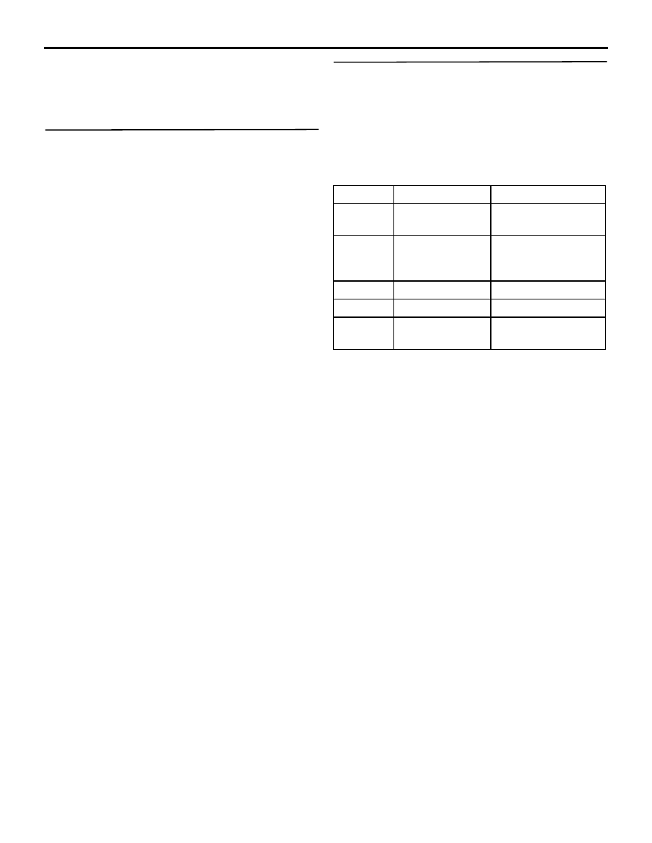
Item No.

Item name

Normal condition

Item 00

HEADLAMP SW ON when the lighting 

switch is at HEAD

Item 01

TAIL LAMP SW

ON when the lighting 
switch is at TAIL or 
HEAD

Item 30

IG SW(IG1)

ON

Item 36

F.FOG LAMP

ON

Item 70

FRONT ECU 
ACK

NORMAL ACK or 
HI-BEAM ACK

SYMPTOM PROCEDURES

SMART WIRING SYSTEM (SWS) USING SWS MONITOR

54C-351

Step 4. Connector check: A-08X front fog lamp 
relay connector

Q: Is the check result normal?

YES : 

Go to Step 5.

NO : 

Repair the defective connector.

Step 5. Check the front fog lamp relay.

Refer to GROUP 54A 

− Fog lamp 

P.54A-93

.

Q: Is the check result normal?

YES : 

Go to Step 6.

NO : 

Replace the front fog lamp relay.

Step 6. Voltage measurement at the A-08X front 
fog lamp relay connector.

(1) Remove the front fog lamp relay, and measure at 

the relay box side.

(2) Check the voltage between the front fog lamp 

relay connector and body earth.

• Voltage between A-08X front fog lamp relay 

connector terminal No.1 and body earth

• Voltage between A-08X front fog lamp relay 

connector terminal No.2 and body earth

OK: System voltage

Q: Is the check result normal?

YES : 

Go to Step 8.

NO : 

Go to Step 7.

Step 7. Check the wiring harness between A-08X 
front fog lamp relay connector (terminal 
Nos.1and 2) and the fusible link (26).

• Check the power supply line for open circuit.

Q: Is the check result normal?

YES : 

The trouble can be an intermittent 

malfunction (Refer to GROUP 00 

− How to 

Cope with Intermittent Malfunction 

P.00-5

).

NO : 

Repair the wiring harness.

Step 8. Connector check: A-14X front-ECU 
connector

Q: Is the check result normal?

YES : 

Go to Step 9.

NO : 

Repair the defective connector.

AC311521AD

Connector: A-08X

1

3

2

4

Front of 
vehicle

Relay box side

AC311521AD

Connector: A-08X

1

3

2

4

Front of 
vehicle

Relay box side

AC310507 BT

Connector A-08X
(Relay box side)

2

4

1

3

AC311521AD

Connector: A-08X

1

3

2

4

Front of 
vehicle

Relay box side

AC311521AB

Connector: A-14X

Relay box side

SYMPTOM PROCEDURES

SMART WIRING SYSTEM (SWS) USING SWS MONITOR

54C-352

Step 9. Check the wiring harness between A-08X 
front fog lamp relay connector terminal No.3 and 
A-14X front-ECU connector terminal No.1.

• Check the output lines for open circuit.

Q: Is the check result normal?

YES : 

Go to Step 10.

NO : 

Repair the wiring harness.

Step 10. Retest the system.

Check that the front fog lamps illuminate normally.

Q: Is the check result normal?

YES : 

The trouble can be an intermittent 

malfunction (Refer to GROUP 00 

− How to 

Cope with Intermittent Malfunction 

P.00-5

).

NO : 

Replace the ETACS-ECU.

AC311937AB

Connectors: A-08X, A-14X

1

3

2

4

Front of 
vehicle

Relay box side

A-08X

A-14X

A-08X

A-14X

SYMPTOM PROCEDURES

SMART WIRING SYSTEM (SWS) USING SWS MONITOR

54C-353

Inspection Procedure O-2: The rear fog lamp do not illuminate normally.

CAUTION

Whenever the ECU is replaced, ensure that the 
input and output signal circuits are normal.

Wire colour code
B : Black     LG : Light green     G : Green     L : Blue     W : White     Y : Yellow     SB : Sky blue
BR : Brown     O : Orange     GR : Gray     R : Red     P : Pink     V : Violet   

ETACS-ECU

FUSIBLE
LINK

REAR FOG
LAMP

REAR 
FOG 
LAMP 
RELAY

30

Rear Fog Lamp Circuit <LHD>


Content   ..  220  221  222  223   ..