Mitsubishi Grandis. Manual - part 220
SYMPTOM PROCEDURES
SMART WIRING SYSTEM (SWS) USING SWS MONITOR
54C-342
NOTE:
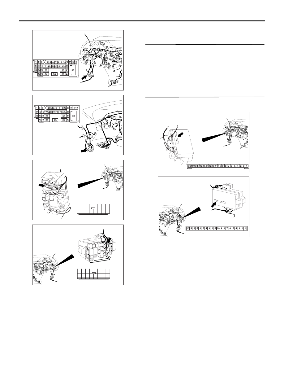
Prior to the wiring harness inspection, check
intermediate connector C-125 and junction block
connector C-203, and repair if necessary.
• Check the output lines for open circuit.
Q: Is the check result normal?
YES :
Go to Step 18.
NO :
Repair the wiring harness.
Step 18. Retest the system.
Check that the turn-signal lamps illuminate normally.
Q: Is the check result normal?
YES :
The trouble can be an intermittent
malfunction (Refer to GROUP 00
− How to
Cope with Intermittent Malfunction
NO :
Replace the headlamp assembly.
Step 19. Connector check: C-219 ETACS-ECU
connector.
Q: Is the check result normal?
YES :
Go to Step 20.
NO :
Repair the defective connector.
AC310613
AD
Connector: C-125 <LHD>
AC310628AB
Connector: C-125 <RHD>
AC310623
Connectors: C-203 <LHD>
AL
Harness side
10
1
6
14
5
12
13
4
11
7
2
3
8
9
Junction block (Front view)
AC310618
Connectors: C-203 <RHD>
AK
Harness side
10
1
6
14
5
12
13
4
11
7
2
3
8
9
Junction block (Front view)
AC310626
Connector: C-219
Junction block (Rear view)
<LHD>
AB
Junction block side
AC310620
Connector: C-219
Junction block
(Rear view)
<RHD>
AB
Junction block side