Mitsubishi Grandis. Manual - part 201
SYMPTOM PROCEDURES
SMART WIRING SYSTEM (SWS) USING SWS MONITOR
54C-266
Inspection Procedure J-4: Vehicle speed-dependent unfolding function does not work normally.
CAUTION
Whenever the ECU is replaced, ensure that the
input and output signal circuits are normal.
COMMENTS ON TROUBLE SYMPTOM
The ETACS-ECU operates this function in
accordance with the input signals below.
• Ignition switch (IG1)
• Vehicle speed signal
If this function does not work normally, these input
signal circuit(s) or the ETACS-ECU may be
defective. In addition, it is possible that the function
except the vehicle speed-dependent unfolding
function has been set by using the customized
function.
POSSIBLE CAUSES
• Malfunction of ETACS-ECU
• Damaged harness wires and connectors
DIAGNOSTIC PROCEDURE
Step 1. Check the SWS monitor customized
function.
Check that "WING MIRROR" is set to "SPEED SEN
FUN" by using the customized function.
Q: Is the check result normal?
YES :
Go to Step 2.
NO :
Set "WING MIRROR" to "SPEED SEN
FUN" by using the customized function.
(Refer to
).
Step 2. Check the electric folding door mirrors
operation.
Check that the door mirror is folded and unfolded
with the remote controlled mirror switch when the
ignition switch is at ACC position.
Q: Is the check result normal?
YES :
Go to Step 3.
NO :
Refer to inspection procedure J-1 "The
electric retractable remote controlled door
mirrors does not work at all
Step 3. ECU check by using the SWS monitor.
Check that the power supply and earth lines to the
ETACS-ECU and the SWS communication lines are
normal.
• Ignition switch: ON
ECUS TO BE CHECKED
• ETACS ECU
OK: "OK" is displayed on the "ETACS ECU"
menu.
Q: Is the check result normal?
YES :
Go to Step 4.
NO :
Refer to Inspection Procedure A-3
"Communication with the ETACS-ECU is
not possible
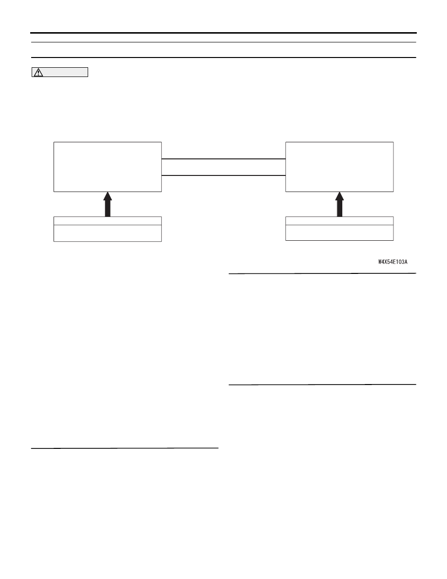
SPEED SIGNAL
COMBINATION METER
CAN COMMUNICATION LINE
(CAN_L LINE)
CAN COMMUNICATION LINE
(CAN_H LINE)
INPUT SIGNAL
ETACS-ECU
INPUT SIGNAL
IGNITION SWITCH (IG1)
Vehicle Speed-Dependent Unfolding Function