Mitsubishi Grandis. Manual - part 181


  Index      Mitsubishi     Mitsubishi Grandis - service repair manual


Search            


Content   ..  179  180  181  182   ..


Mitsubishi Grandis. Manual - part 181


SYMPTOM PROCEDURES

SMART WIRING SYSTEM (SWS) USING SWS MONITOR

54C-186

YES : 

Go to Step 4.

NO : 

Refer to inspection procedure Q-5 "The 
driver's door switch signal is not received 

P.54C-474

 <LH drive vehicles> or 

P.54C-476

 <RH drive vehicles>."

Step 4. Retest the system.

Check that the power window timer function works 
normally.

Q: Is the check result normal?

YES : 

The trouble can be an intermittent 

malfunction (Refer to GROUP 00, How to 
Cope with Intermittent Malfunction 

P.00-5

).

NO : 

Replace the power window main switch.

KEYLESS ENTRY SYSTEM

Inspection Procedure E-1: Keyless entry system does not work.

CAUTION

Whenever the ECU is replaced, ensure that the 
input and output signal circuits are normal.

COMMENTS ON TROUBLE SYMPTOM

If the keyless entry system does not work normally, 
the input signal circuits to the components below or 
the ETACS-ECU may be defective.

• Key reminder switch

• All of the door switches

• Keyless entry transmitter

• Driver's door lock actuator

POSSIBLE CAUSES

• Malfunction of the key reminder switch

• Malfunction of the door switches

• Malfunction of the keyless entry transmitter

• Malfunction of the driver's door lock actuator

• Malfunction of the ETACS-ECU

• Damaged harness wires and connectors

DIAGNOSIS PROCEDURE

Step 1. Check the operation of the central door 
locking system.

Check that the central door locking system works 
normally.

Q: Is the check result normal?

YES : 

Go to Step 2

NO : 

Refer to Inspection Procedure C-1 "central 
door locking system does not work 

P.54C-106

."

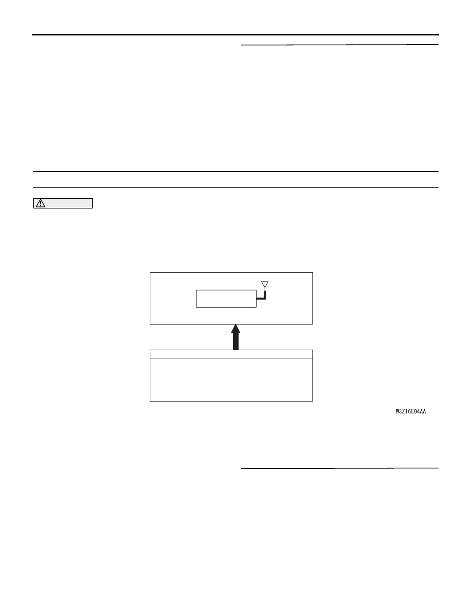
Keyless Entry System Function Circuit

ETACS-ECU

INPUT SIGNAL

· ALL OF THE DOOR SWITCHES
· DRIVER'S DOOR LOCK ACTUATOR SWITCH
· KEYLESS ENTRY TRANSMITTER SWITCH
· KEY REMINDER SWITCH

KEYLESS ENTRY
RECEIVER

SYMPTOM PROCEDURES

SMART WIRING SYSTEM (SWS) USING SWS MONITOR

54C-187

Step 2. ECU check by using the SWS monitor.

Check that the power supply and earth lines to the 
ETACS-ECU and the SWS communication lines are 
normal.

• Ignition switch: OFF

ECUS TO BE CHECKED

• ETACS ECU

OK: "OK" is displayed on the "ETACS ECU" 
menu.

Q: Is the check result normal?

YES : 

Go to Step 3.

NO : 

Refer to Inspection Procedure A-3 
"Communication with the ETACS-ECU is 
not possible 

P.54C-63

."

Step 3. Use the SWS monitor to examine the 
keyless entry system for signal reception.

Check the condition of the keyless entry transmitter.

OK: By operating the switch as shown in the 
table above, relevant normal conditions are 
displayed.

Q: Are normal condition displayed?

YES : 

Go to Step 4.

NO : 

Refer to Inspection Procedure Q-23 "Each 
switch signal of the keyless entry transmitter 
is not received 

P.54C-562

."

Step 4. SWS monitor data list.

Check the SWS communication input signal, which 
are related to the keyless entry system.

<Selected item> ETACS

• Driver’s door: Lock → Unlock

OK: Normal condition is displayed.

Q: Is normal condition displayed?

YES : 

Go to Step 5.

NO : 

Refer to inspection procedure Q-5 "The 
driver's door switch signal is not received 
<LH drive vehicles>

P.54C-474

 or <RH drive 

vehicles>

P.54C-476

."

Step 5. ETACS switch data by using the SWS 
monitor.

Check the ETACS-ECU signal related to the keyless 
entry system.

• Ignition switch: OFF (key inserted)

• Open the doors other than the driver's door 

(including the tailgate).

OK: Normal conditions are displayed for all 
the items.

Q: Are the check result normal?

Normal conditions displayed for all the items : 

Go 

to Step 6.

Normal condition is not displayed for item No.03. : 

Refer to inspection procedure Q-11 "The 
key reminder switch signal is not received 

P.54C-493

."

Normal condition is not displayed for item 05, 07, 
41 or 42. : 

Refer to inspection procedure Q-14 "All 

the door switch signals are not received 

P.54C-505

."

Step 6. Retest the system.

Check the keyless entry system works normally.

Q: Is the check result normal?

YES : 

The trouble can be an intermittent 

malfunction (Refer to GROUP 00 

− How to 

Cope with Intermittent Malfunction 

P.00-5

).

NO : 

Replace the ETACS-ECU.

Operation switch

Normal conditions 
(received signal)

LOCK

LOCK

UNLOCK

UNLOCK

Item No.

Item name

Normal condition

Item 32

DR DOR SW

from OFF to ON

Item No. Item name

Normal condition

Item 03

KEY REMINSW

OFF

Item 05

PASS DOORSW

from OFF to ON

Item 07

TRK LID LASW

from OFF to ON

Item 41

R.DOOR (RH) SW from OFF to ON

Item 42

R.DOOR (LH) SW from OFF to ON

SYMPTOM PROCEDURES

SMART WIRING SYSTEM (SWS) USING SWS MONITOR

54C-188

INSPECTION PROCEDURE E-2: Keyless Entry hazard lamp answerback function or the Room Lamp 
Answerback Function does not Work Normally.

CAUTION

Whenever the ECU is replaced, ensure that the 
input and output signal circuits are normal.

COMMENTS ON TROUBLE SYMPTOM

If the hazard warning lamp and the room lamp work 
normally, the ETACS-ECU may be defective.
Alternatively, it is possible that the keyless entry 
hazard lamp answerback function was disabled by 
the customize function.

POSSIBLE CAUSES

• Defective turn-signal lamp

• Malfunction of the room lamp

• Malfunction of the ETACS-ECU

• Damaged harness wires and connectors

DIAGNOSIS PROCEDURE

Step 1. Check the operation of the hazard 
warning lamp.
Check that the hazard warning lamps illuminate 
normally.

Q: Is the check result normal?

YES : 

Go to Step 2.

NO : 

Refer to inspection procedure N-2 "The 
hazard warning lamps do not illuminate 

P.54C-321

".

Step 2. Check the operation of the room lamps.
Check that the room lamps illuminate normally.

Q: Is the check result normal?

YES : 

Go to Step 3.

NO : 

Refer to inspection procedure P-2 "The 
room lamp does not illuminate normally 
<Vehicles with keyless entry>

P.54C-383

."

Step 3. Check the operation of the keyless entry 
system.
If the keyless entry system is operated, check that 
the doors can be locked and unlocked normally.

Q: Is the check result normal?

YES : 

Go to Step 4.

NO : 

Refer to inspection procedure E-1 "Keyless 
entry system does not work 

P.54C-186

."

Step 4. Customize function by using the SWS 
monitor.

Check that "KEYLESS HAZARD" is set to other than 
"NO BLINK" by using the SWS monitor 
customisation function.

• LOCK1, UNLOCK2

• LOCK1, UNLOCK0

• LOCK0, UNLOCK2

• LOCK2, UNLOCK1

• LOCK2, UNLOCK0

• LOCK0, UNLOCK1

Q: Is the check result normal?

YES : 

Go to Step 5 .

NO : 

Set "KEYLESS HAZARD" to other than "NO 
BLINK" by using the SWS monitor 
customisation function (Refer to 

P.54C-574

).

Step 5. ECU check by using the SWS monitor

Check that the power supply and earth lines to the 
ETACS-ECU and the SWS communication lines are 
normal.

• Ignition switch: OFF

ECU TO BE CHECKED

• ETACS ECU

OK: "OK" is displayed on the "ETACS ECU" 
menu.

Q: Is the check result normal?

YES : 

Go to Step 6.

NO : 

Refer to Inspection Procedure A-3 
"Communication with the ETACS-ECU is 
not possible 

P.54C-63

."

Step 6. Retest the system.

Check that the keyless entry hazard lamp 
answerback function or the room lamp answerback 
function work normally.

Q: Is the check result normal?

YES : 

The trouble can be an intermittent 

malfunction (Refer to GROUP 00 

− How to 

Cope with Intermittent Malfunction 

P.00-5

).

NO : 

Replace the ETACS-ECU.

SYMPTOM PROCEDURES

SMART WIRING SYSTEM (SWS) USING SWS MONITOR

54C-189

INSPECTION PROCEDURE E-3: Encrypted Code cannot be Registered.

CAUTION

Whenever the ECU is replaced, ensure that the 
input and output signal circuits are normal.

COMMENTS ON TROUBLE SYMPTOM

If the encrypted code registration mode is not 
entered, the key reminder switch, the hazard warning 
lamp switch or the ETACS-ECU may be defective.
If the registration is not possible although the 
registration mode is entered, the keyless entry 
transmitter or the ETACS-ECU may be defective.

POSSIBLE CAUSES

• Malfunction of the keyless entry transmitter

• Malfunction of the ETACS-ECU

• Damaged harness wires and connectors

DIAGNOSIS PROCEDURE

Step 1. Check the encrypted code registration 
mode.

Check that the encrypted code registration mode is 
entered.

Q: Is the check result normal?

YES : 

Go to Step 3.

NO : 

Go to Step 2.

Step 2. ETACS switch data by using the SWS 
monitor.

Check the relevant ETACS-ECU signal before 
entering the encrypted code registration mode.

• Ignition switch: OFF (key inserted)

• Hazard lamp switch: ON

OK: Normal conditions are displayed for all 
the items.

Q: Are the check result normal?

Normal conditions displayed for all the items : 

Go 

to Step 3.

Normal condition is not displayed for item No.03. : 

Refer to inspection procedure Q-11 "The 
key reminder switch signal is not received 

P.54C-493

."

Normal condition is not displayed for item No.04. : 

Refer to inspection procedure Q-12 "The 
hazard warning lamp switch signal is not 
received 

P.54C-497

."

INPUT SIGNAL

ETACS-ECU

· HAZARD WARNING LAMP SWITCH
· KEYLESS ENTRY TRANSMITTER SWITCH
· KEY REMINDER SWITCH

Encrypted Transmitter Code Register Mode

Item No. Item name

Normal condition

Item 03

KEY REMIN SW

OFF

Item 04

HAZARD LMP SW ON (only when 

switch is operated)


Content   ..  179  180  181  182   ..