Mitsubishi Grandis. Manual - part 167


  Index      Mitsubishi     Mitsubishi Grandis - service repair manual


Search            


Content   ..  165  166  167  168   ..


Mitsubishi Grandis. Manual - part 167


SYMPTOM PROCEDURES

SMART WIRING SYSTEM (SWS) USING SWS MONITOR

54C-130

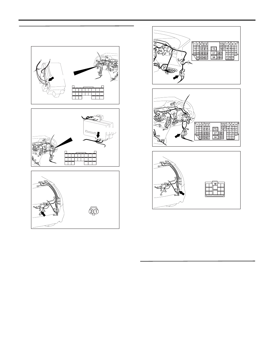
Step 9. Check the wiring harness from C-221 
ETACS-ECU connector terminal No.61 to G-17 
tailgate lock actuator connector terminal No.1.

NOTE: 

Prior to the wiring harness inspection, check 
intermediate connector C-16 and G-14, and repair if 
necessary.

• Check the input and output lines for open circuit.

Q: Is the check result normal?

YES : 

Go to Step 10.

NO : 

Repair the wiring harness.

Step 10. Retest the system.

Check that the tailgate lock works normally.

Q: Is the check result normal?

YES : 

The trouble can be an intermittent 

malfunction (Refer to GROUP 00 

− How to 

Cope with Intermittent Malfunction 

P.00-5

).

NO : 

Replace the ETACS-ECU.

AC310626

Connector: C-221

Junction block (Rear view)

<LHD>

AC

51

52

53

54

55

56

57

58

59

60

61

62

63

64

65

66

67

68

69

70

71

72

73

74

Harness side

C-221(GR)

AC310620

Connector: C-221

Junction block 
(Rear view)

<RHD>

AC

51

52

53

54

55

56

57

58

59

60

61

62

63

64

65

66

67

68

69

70

71

72

73

74

Harness side

C-221(GR)

AC310222

Connector: G-17

Harness side

AD

G-17(B)

AC310615

AE

Connector: C-16 <LHD>

AC310631 AD

Connector: C-16 <RHD>

AC310222

Connector: G-14

AF

2

1

4

3

13

8

11

10

5

7

12

6

14

9

SYMPTOM PROCEDURES

SMART WIRING SYSTEM (SWS) USING SWS MONITOR

54C-131

POWER WINDOWS

Inspection Procedure D-1: Power windows do not work at all.

CAUTION

Whenever the ECU is replaced, ensure that the 
input and output signal circuits are normal.

Power Window Relay Circuit

FUSIBLE 
LINK

5

POWER WINDOW
RELAY

ETACS-ECU

POWER WINDOW
MAIN SWITCH

POWER 
WINDOW 
SUB 
SWITCH 
(FRONT: RH)

POWER 
WINDOW 
SUB 
SWITCH 
(REAR: LH)

POWER 
WINDOW 
SUB 
SWITCH 
(REAR: RH)

CPU

Wire colour code
B : Black 
LG : Light green
G : Green
L: Blue 
W : White
Y: Yellow
SB : Sky blue
BR : Brown 
O : Orange
GR : Gray  
R : Red 
P : Pink  
V : Violet       

J/B SIDE

SYMPTOM PROCEDURES

SMART WIRING SYSTEM (SWS) USING SWS MONITOR

54C-132

COMMENTS ON TROUBLE SYMPTOM

If the power windows do not work at all, the power 
window relay, the power window main switch or the 
ETACS-ECU may be defective.

POSSIBLE CAUSES

• Malfunction of the power window relay

• Malfunction of the power window main switch

• Malfunction of the ETACS-ECU

• Damaged harness wires and connectors

DIAGNOSIS PROCEDURE

Step 1. ECU check by using the SWS monitor

Check that the power supply and earth lines to the 
ETACS-ECU and the power window main switch 
(power window module) and the SWS 
communication lines are normal.

• Turn the ignition switch to the ON position.

ECUS TO BE CHECKED

• ETACS ECU

• P/W MODULE

OK: "OK" are displayed for all the items

Q: Are the check result normal?

"OK" are displayed for all the items : 

Go to Step 2.

"NG" is displayed on the "ETACS ECU" menu. : 

Refer to Inspection Procedure A-3 
"Communication with the ETACS-ECU is 
not possible 

P.54C-63

."

"NG" is displayed on the "P/W MODULE" menu. : 

Refer to Inspection Procedure A-5 
"Communication with the power window 
main switch (power window module) is not 
possibl

P.54C-77

."

Step 2. Function diagnosis by using the SWS 
monitor

Check the SWS communication signal, which are 
related to the power windows.

<Selected item> POWER WINDOW

• Turn the ignition switch to the ON position.

• Power window main switch: UP

OK: Normal conditions are displayed for all 
the items.

Q: Are the check result normal?

Normal conditions are displayed for all the items : 

Go to Step 3.

Normal condition is not displayed for item No.30 : 

Refer to inspection procedure Q-2 "The 
ignition switch (IG1) signal is not received 

P.54C-460

."

Normal condition is not displayed for item No.33 : 

Replace the ETACS-ECU.

Normal condition is not displayed for item No.71 : 

Replace the power window main switch.

Step 3. SWS monitor data list

Check the SWS communication signal, which are 
related to the power windows.

<Selected item> DOOR CNT. COM.

• Insert the probe (For the insertion point, refer to 

P.54C-10

).

• Turn the ignition switch to the ON position.

• Power window main switch: UP

OK: Normal condition is displayed.

Q: Is the check result normal?

YES : 

Go to Step 4.

NO : 

Replace the power window main switch.

Step 4. Retest the system.

Check that the all the power windows work.

Q: Is the check result normal?

Item No. Item name

Normal condition

Item 30

IG SW (IG1)

ON

Item 33

P/W SW ACCEPT PERMIT

Item 71

P/W ECU ACK

INPUT CHECK (only 
momentarily when 
switch is operated)

Item No.

Item name

Normal 
condition

Item C0

PASS DOR UP

ON

SYMPTOM PROCEDURES

SMART WIRING SYSTEM (SWS) USING SWS MONITOR

54C-133

YES : 

The trouble can be an intermittent 

malfunction (Refer to GROUP 00 

− How to 

Cope with Intermittent Malfunction 

P.00-5

).

NO : 

Replace the power window main switch.

Inspection Procedure D-2: Driver's power window does not work by means of the power window main 
switch. <LH drive vehicles>

Power Window (front: LH) Circuit <LHD>

FUSIBLE 
LINK

5

POWER 
WINDOW 
RELAY

ETACS-ECU

POWER 
WINDOW
MAIN SWITCH

POWER WINDOW
MOTOR 
(FRONT: LH)

Wire colour code
B : Black     LG : Light green     G : Green     L : Blue     W : White     Y : Yellow     SB : Sky blue
BR : Brown     O : Orange     GR : Gray     R : Red     P : Pink     V : Violet   

CPU

FRONT
 (LH)


Content   ..  165  166  167  168   ..