Mitsubishi Grandis. Manual - part 164
SYMPTOM PROCEDURES
SMART WIRING SYSTEM (SWS) USING SWS MONITOR
54C-118
YES :
The trouble can be an intermittent
malfunction (Refer to GROUP 00
− How to
Cope with Intermittent Malfunction
NO :
Repair the wiring harness.
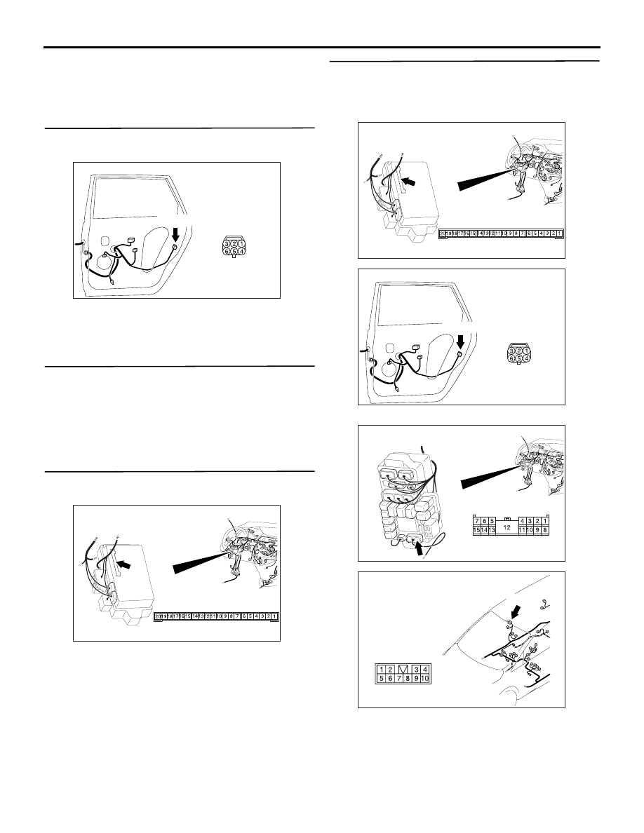
Step 10. Connector check: F-20 door lock
actuator (rear: RH) connector
Q: Is the check result normal?
YES :
Go to Step 11.
NO :
Repair the defective connector.
Step 11. Check the door lock actuator (rear: RH).
Check that the door lock actuator (rear: RH) is in
good condition. Refer to GROUP 42
− Door
Q: Is the check result normal?
YES :
Go to Step 12.
NO :
Replace the door lock actuator (rear: RH).
Step 12. Connector check: C-219 ETACS-ECU
connector
Q: Is the check result normal?
YES :
Go to Step 13.
NO :
Repair the defective connector.
Step 13. Check the wiring harness from C-219
ETACS-ECU connector terminal Nos.12 and 13 to
F-20 door lock actuator (rear: RH) connector
terminal Nos.4 and 6.
NOTE:
Prior to the wiring harness inspection, check D-03
intermediate connector and C-210 junction block
connector, and repair if necessary.
• Check the input and output lines for open circuit.
Q: Is the check result normal?
AC310216
Connector: F-20
Harness side
AE
F-20(B)
AC310626AD
Connector: C-219 <LHD>
Junction block (Rear view)
Junction block side
AC310626AD
Connector: C-219 <LHD>
Junction block (Rear view)
Junction block side
AC310216
Connector: F-20
Harness side
AE
F-20(B)
AC310623
Connector: C-210
AN
<LHD>
Junction block (Front view)
Harness side
AC310633 AB
Connector: D-03 <LHD>
D-03(B)