Mitsubishi Grandis. Manual - part 148


  Index      Mitsubishi     Mitsubishi Grandis - service repair manual


Search            


Content   ..  146  147  148  149   ..


Mitsubishi Grandis. Manual - part 148


SYMPTOM PROCEDURES

SMART WIRING SYSTEM (SWS) USING SWS MONITOR

54C-54

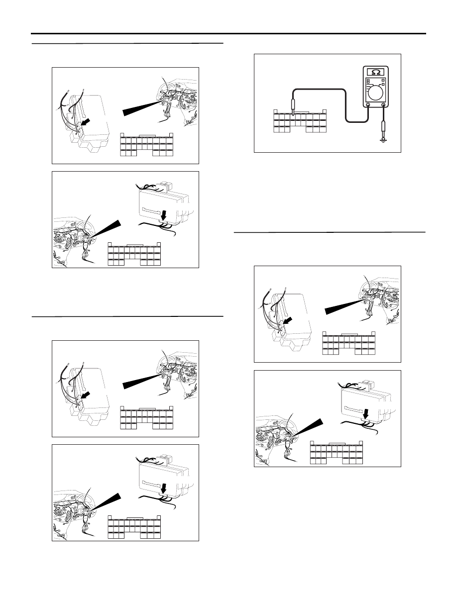
Step 3. Connector check: C-221 ETACS-ECU 
connector

Q: Is the check result normal?

YES : 

Go to Step 4.

NO : 

Repair the defective connector.

Step 4. Resistance measurement at the C-221 
ETACS-ECU connector.

(1) Disconnect the connector, and measure at the 

wiring harness side.

(2) Resistance between C-221 ETACS-ECU 

connector terminal No.56 and body earth

OK: 2 

 or less

Q: Is the check result normal?

YES : 

Go to Step 6.

NO : 

Go to Step 5.

Step 5. Check the wiring harness between C-221 
ETACS-ECU connector terminal No.56 and body 
earth.

• Check the earth wires for open circuit.

Q: Are the check results normal?

YES : 

The trouble can be an intermittent 

malfunction (Refer to GROUP 00 

− How to 

Cope with Intermittent Malfunction 

P.00-5

).

NO : 

Repair the wiring harness.

AC310626

Connector: C-221

Junction block (Rear view)

<LHD>

AC

51

52

53

54

55

56

57

58

59

60

61

62

63

64

65

66

67

68

69

70

71

72

73

74

Harness side

C-221(GR)

AC310620

Connector: C-221

Junction block 
(Rear view)

<RHD>

AC

51

52

53

54

55

56

57

58

59

60

61

62

63

64

65

66

67

68

69

70

71

72

73

74

Harness side

C-221(GR)

AC310506

51

52

53

54

55

56

57

58

59

60

61

62

63

64

65

66

67

68

69

70

71

72

73

74

AC310506DB

Connector C-221
(Harness side)

AC310626

Connector: C-221

Junction block (Rear view)

<LHD>

AC

51

52

53

54

55

56

57

58

59

60

61

62

63

64

65

66

67

68

69

70

71

72

73

74

Harness side

C-221(GR)

AC310620

Connector: C-221

Junction block 
(Rear view)

<RHD>

AC

51

52

53

54

55

56

57

58

59

60

61

62

63

64

65

66

67

68

69

70

71

72

73

74

Harness side

C-221(GR)

SYMPTOM PROCEDURES

SMART WIRING SYSTEM (SWS) USING SWS MONITOR

54C-55

Step 6. Connector check: C-126 diagnosis 
connector

Q: Is the check result normal?

YES : 

Go to Step 7.

NO : 

Repair the defective connector.

Step 7. Check the wiring harness from C-221 
ETACS-ECU connector terminal Nos.51 and 67 to 
C-126 diagnosis connector terminal Nos.9 and 1.

• Check the communication lines for open circuit.

Q: Are the check results normal?

YES : 

Replace the ETACS-ECU.

NO : 

Repair the wiring harness.

AC310613

AO

Connector: C-126 <LHD>

Harness side 
(Front side)

C-126 (B)

AC310631AK

Connector: C-126 <RHD>

C-126 (B)

Harness side 
(Front side)

AC310613

AO

Connector: C-126 <LHD>

Harness side 
(Front side)

C-126 (B)

AC310631AK

Connector: C-126 <RHD>

C-126 (B)

Harness side 
(Front side)

AC310626

Connector: C-221

Junction block (Rear view)

<LHD>

AC

51

52

53

54

55

56

57

58

59

60

61

62

63

64

65

66

67

68

69

70

71

72

73

74

Harness side

C-221(GR)

AC310620

Connector: C-221

Junction block 
(Rear view)

<RHD>

AC

51

52

53

54

55

56

57

58

59

60

61

62

63

64

65

66

67

68

69

70

71

72

73

74

Harness side

C-221(GR)

SYMPTOM PROCEDURES

SMART WIRING SYSTEM (SWS) USING SWS MONITOR

54C-56

Inspection Procedure A-2: Communication with the column switch (column-ECU) is not possible.

CAUTION

Whenever the ECU is replaced, ensure that the 
power supply circuit, the earthing circuit and the 
communication circuit are normal.

FUSIBLE
LINK

26

IGNITION
SWITCH (IG1)

RELAY
BOX

COLUMN
SWITCH

Wire colour code
B : Black
LG : Light green
G : Green
L: Blue
W : White
Y: Yellow
SB : Sky blue
BR : Brown
O : Orange
GR : Gray
R : Red
P : Pink
V : Violet

COLUMN-ECU

ETACS-ECU

DIAGNOSIS
CONNECTOR

FRONT SIDE

Column Switch Power Supply and SWS Communication Circuit <LHD>

SYMPTOM PROCEDURES

SMART WIRING SYSTEM (SWS) USING SWS MONITOR

54C-57

COMMENTS ON TROUBLE SYMPTOM

The power supply circuit to the column switch 
(column-ECU) may be defective. If the wiring 
harness of the battery power supply circuit for the 
ECU (column switch terminal No.1) is defective, also 
check the power supply circuit to the ignition switch 
(IG1) (column switch terminal No.9) and repair if 
necessary.

TROUBLESHOOTING HINTS

• Malfunction of the ETACS-ECU

• Malfunction of the column switch

• Damaged harness wires and connectors

FUSIBLE
LINK

26

IGNITION
SWITCH (IG1)

RELAY
BOX

COLUMN
SWITCH

Wire colour code
B : Black
LG : Light green
G : Green
L: Blue
W : White
Y: Yellow
SB : Sky blue
BR : Brown
O : Orange
GR : Gray
R : Red
P : Pink
V : Violet

COLUMN-ECU

ETACS-ECU

DIAGNOSIS
CONNECTOR

FRONT SIDE

Column Switch Power Supply and SWS Communication Circuit <RHD>


Content   ..  146  147  148  149   ..