Mitsubishi Grandis. Manual - part 132


  Index      Mitsubishi     Mitsubishi Grandis - service repair manual


Search            


Content   ..  130  131  132  133   ..


Mitsubishi Grandis. Manual - part 132


INPUT SIGNAL PROCEDURES

SMART WIRING SYSTEM (SWS) NOT USING SWS MONITOR

54B-525

YES : 

Go to Step 2.

NO : 

Refer to inspection procedure A-2 "Check 
the ETACS-ECU battery power supply 
circuit 

P.54B-87

."

Step 2. Connector check: C-219 ETACS-ECU 
connector

Q: Is the check result normal?

YES : 

Go to Step 3.

NO : 

Repair the defective connector.

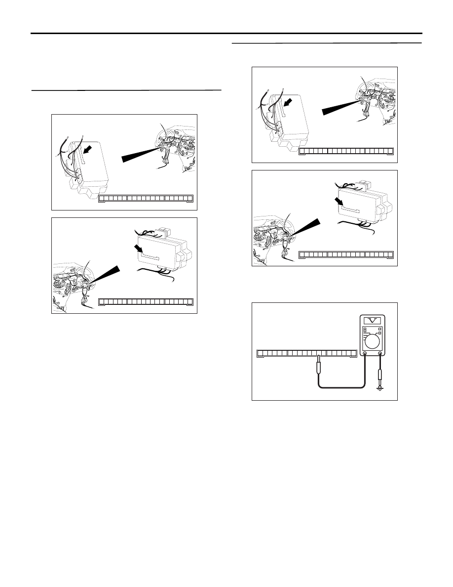
Step 3. Voltage measurement at the C-219 
ETACS-ECU connector.

(1) Remove the ETACS-ECU, and measure at the 

junction block side.

(2) Turn the ignition switch to the ON position.

(3) Voltage between C-219 ETACS-ECU connector 

terminal No.8 and body earth

OK: System voltage

Q: Is the check result normal?

YES : 

Go to Step 5.

NO : 

Go to Step 4.

AC312037

Connector: C-219

Junction block (Rear view)

Junction block side

AB

3

1

2

14

4

5

7 6

8

1110 9

1312

17

15

16

18

19

20

<LHD>

AC312047

Connector: C-219

Junction block (Rear view)

Junction block side

AB

3

1

2

14

4

5

7 6

8

1110 9

1312

17

15

16

18

19

20

<RHD>

AC312731AC

Connector C-219
(Junction block side)

2019

7

13

17

18

1615 14

10

11

12

9 8

2

6 5

3

4

1

INPUT SIGNAL PROCEDURES

SMART WIRING SYSTEM (SWS) NOT USING SWS MONITOR

54B-526

Step 4. Check the wiring harness between C-219 
ETACS-ECU connector terminal No.8 and the 
ignition switch (IG1).

NOTE: 

Prior to the wiring harness inspection, check junction 
block connector C-202, and repair if necessary.

• Check the power supply line to the ignition switch 

(IG1) for open circuit.

Q: Is the check result normal?

YES : 

The trouble can be an intermittent 

malfunction (Refer to GROUP 00 

− How to 

Cope with Intermittent Malfunction 

P.00-5

).

NO : 

Repair the wiring harness.

Step 5. Voltage measurement at the C-219 
ETACS-ECU connector.

(1) Remove the ETACS-ECU, and measure at the 

junction block side.

(2) Turn the ignition switch to the ACC position.

(3) Voltage between terminal 4 and body earth

OK: System voltage

Q: Is the check result normal?

YES : 

Go to Step 7.

NO : 

Go to Step 6.

AC312037

Connector: C-219

Junction block (Rear view)

Junction block side

AB

3

1

2

14

4

5

7 6

8

1110 9

1312

17

15

16

18

19

20

<LHD>

AC312047

Connector: C-219

Junction block (Rear view)

Junction block side

AB

3

1

2

14

4

5

7 6

8

1110 9

1312

17

15

16

18

19

20

<RHD>

AC312035AB

Connector: C-202

Harness side

<LHD>

Junction block (Front view)

AC312045

AB

Connector: C-202

Junction block (Front view)

Harness side

<RHD>

AC312037

Connector: C-219

Junction block (Rear view)

Junction block side

AB

3

1

2

14

4

5

7 6

8

1110 9

1312

17

15

16

18

19

20

<LHD>

AC312047

Connector: C-219

Junction block (Rear view)

Junction block side

AB

3

1

2

14

4

5

7 6

8

1110 9

1312

17

15

16

18

19

20

<RHD>

AC312731AF

Connector C-219
(Junction block side)

2019

7

13

17

18

1615 14

10

11

12

9 8

2

6 5

3

4

1

INPUT SIGNAL PROCEDURES

SMART WIRING SYSTEM (SWS) NOT USING SWS MONITOR

54B-527

Step 6. Check the wiring harness between C-219 
ETACS-ECU connector terminal No.4 and the 
ignition switch (ACC).

NOTE: 

AC312037

Connector: C-219

Junction block (Rear view)

Junction block side

AB

3

1

2

14

4

5

7 6

8

1110 9

1312

17

15

16

18

19

20

<LHD>

AC312047

Connector: C-219

Junction block (Rear view)

Junction block side

AB

3

1

2

14

4

5

7 6

8

1110 9

1312

17

15

16

18

19

20

<RHD>

INPUT SIGNAL PROCEDURES

SMART WIRING SYSTEM (SWS) NOT USING SWS MONITOR

54B-528

Prior to the wiring harness inspection, check joint 
connector C-32 <LH drive vehicles>, C-01 <RH drive 
vehicles> junction block connector C-203 or 
intermediate connector C-125, and repair if 
necessary.

• Check the power supply line to the ignition switch 

(ACC) for open circuit.

Q: Is the check result normal?

YES : 

The trouble can be an intermittent 

malfunction (Refer to GROUP 00 

− How to 

Cope with Intermittent Malfunction 

P.00-5

).

NO : 

Repair the wiring harness.

Step 7. Retest the system.
Check that the interior lamp loaded signal is received 
normally.

Q: Is the check result normal?

YES : 

The trouble can be an intermittent 

malfunction (Refer to GROUP 00 

− How to 

Cope with Intermittent Malfunction 

P.00-5

).

NO : 

Replace the ETACS-ECU.

AC312043AC

Connector: C-01<RHD>

AC310613

AG

Connector: C-32 <LHD>

AC312035AD

Connector: C-203 <LHD>

Junction block (Front view)

Harness side

10

1

6

14

5

12

13

4

11

7

2

3

8

9

AC312045

AD

Connector: C-203 <RHD>

Harness side

Junction block (Front view)

10

1

6

14

5

12

13

4

11

7

2

3

8

9

AC312031

AJ

Connector: C-125 <LHD>

38

1213

11

26

14

1

20

6

232425

37

31

36

30

10

9

2122

35

8

7

34

17

29

1819

5

4

1516

33

28

32

27

3

2

AC312041AD

Connector: C-125 <RHD>

38

1213

11

26

14

1

20

6

232425

37

31

36

30

10

9

2122

35

8

7

34

17

29

1819

5

4

1516

33

28

32

27

3

2


Content   ..  130  131  132  133   ..