Mitsubishi Grandis. Manual - part 1047


  Index      Mitsubishi     Mitsubishi Grandis - service repair manual


Search            


Content   ..  1045  1046  1047  1048   ..


Mitsubishi Grandis. Manual - part 1047


SEAT BELTS WITH PRE-TENSIONER

SUPPLEMENTAL RESTRAINT SYSTEM (SRS)

52B-240

NOTE: The figure shows the seat belt with 
pre-tensioner (RH).

REMOVAL SERVICE POINTS
<<A>>NEGATIVE BATTERY CABLE 
DISCONNECTION

DANGER

Wait at least 60 seconds after disconnecting 
the battery cable before doing any further 
work (Refer to 

P.52B-7

).

WARNING

Battery posts, terminals and related 
accessories contain lead and lead 
compounds. WASH HANDS AFTER 
HANDLING.

Disconnect the negative battery cable from the 
battery and tape the terminal to prevent accidental 
connection and air bag(s) deployment.

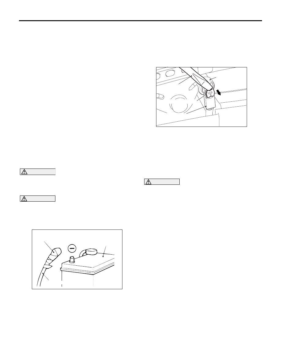
<<B>>PRE-TENSIONER CONNECTOR 
DISCONNECTION

1. Use a flat-tipped screwdriver to pull out forward 

and unlock the locking button of the harness-side 
connector.

2. Disconnect the pre-tensioner connector.

INSTALLATION SERVICE POINTS
>>A<< PRE-INSTALLATION INSPECTION

WARNING

Dispose of air bag modules only according 
to the specified procedure. (Refer to 

P.52B-246

).

1. When installing the new air bag modules and 

clock spring, refer to “INSPECTION” (

P.52B-230

).

2. Connect the negative battery cable.

Removal steps

<<A>>

1. Negative battery cable connection
2. Seat belt shoulder anchor bolt
3. Seat belt lower anchor bolt

Centre pillar trim, lower (Refer to 
GROUP 52A, Trims 

P.52A-10

.)

<<B>>

4. Pre-tensioner connector connection
5. Seat belt with pre-tensioner

Installation steps

>>A<<

Pre-installation inspection

5. Seat belt with pre-tensioner

>>B<<

4. Pre-tensioner connector connection

Centre pillar trim, lower (Refer to 
GROUP 52A, Trims 

P.52A-10

.)

3. Seat belt lower anchor bolt
2. Seat belt shoulder anchor bolt
1. Negative battery cable connection

>>C<<

Post-installation inspection

ACX00583

Insulating tape

Battery

Battery cable (–)

AC

AC300147AB

Pre-tensioner
connector

Flat-tip screw
driver

Locking button

Harness side connector

SEAT BELTS WITH PRE-TENSIONER

SUPPLEMENTAL RESTRAINT SYSTEM (SRS)

52B-241

CAUTION

To prevent damage to MUT-III MB991958, always 
turn the ignition switch to the "LOCK" (OFF) 
position before connecting or disconnecting 
MUT-III MB991958.
3. Connect MUT-III MB991958 to the diagnosis 

connector.

4. Turn the ignition switch to the “ON” position.
5. Check DTCs using MUT-III MB991958 to ensure 

entire SRS operates properly.
At this time, check that no diagnosis code except 
B1400, B1410, B1480 and B1490 are set.

DANGER

Wait at least 60 seconds after disconnecting 
the battery cable before doing any further 
work. (Refer to 

P.52B-7

).

WARNING

Battery posts, terminals and related 
accessories contain lead and lead 
compounds. WASH HANDS AFTER 
HANDLING.

6. Turn the ignition switch to the "LOCK" (OFF) 

position. Disconnect the negative battery cable 
and tape the terminal to prevent accidental 
connection and air bags deployment.

>>B<< PRE-TENSIONER CONNECTOR 
CONNECTION

Connect the pretensioner connector then securely 
lock the locking button of the harness-side 
connector.

>> C<< POST-INSTALLATION 
INSPECTION

1. Connect the negative battery cable.
2. Turn the ignition key to "ON" position.

3. Does the SRS warning lamp illuminate for about 7 

seconds, and then remain extinguished for at 
least 5 seconds after turning OFF?

4. If no, refer to troubleshooting (Refer to

P.52B-13

).

INSPECTION

M1524004200308

WARNING

If any component damage is found during 
the following inspection, replace the seat 
belt with pre-tensioner with a new one. 
Dispose of the old one according to the 
specified procedure (Refer to 

P.52B-246

).

Never attempt to measure the circuit 
resistance of the seat belt pre-tensioner 
even if you are using the specified tester. 
If the circuit resistance is measured with a 
tester, accidental seat belt pre-tensioner 
operation will result in serious personal 
injury.

1. Check the pre-tensioner deployment section for 

dents and deformation.

2. Check the harness and connector for damage and 

the terminals for deformation.

AC302297

AC310120

AB

MB991827

16-pin

MB991910

MB991824

AC312486

SRS warning lamp

AB

SEAT SLIDE SENSOR

SUPPLEMENTAL RESTRAINT SYSTEM (SRS)

52B-242

SEAT SLIDE SENSOR

M1524025300032

REMOVAL AND INSTALLATION

WARNING

Never attempt to disassemble or repair the seat slide sensor. If faulty, replace it. 

Do not drop or subject the seat slide sensor to impact or vibration. Replace the seat slide 
sensor, if dents, cracking, deformation, or rust are present. 

Pre-removal Operation
• Turn the ignition key to the "LOCK" (OFF) position.

AC312580

AC312579

2

9 ± 2 N·m

1

AB

Front seat (Driver's side)

Removal steps

<<A>>

1.

Negative battery cable connection

Front seat <Driver’s side> (Refer to 
GROUP 52A, Front seat assembly 

P.52A-21

).

2.

Seat slide sensor

Installation steps

>>A<<

Pre-installation inspection

>>B<<

2.

Seat slide sensor

Front seat <Driver’s side> (Refer to 
GROUP 52A, Front seat assembly 

P.52A-21

).

1.

Negative battery cable connection

>>C<<

Post-installation inspection

SEAT SLIDE SENSOR

SUPPLEMENTAL RESTRAINT SYSTEM (SRS)

52B-243

REMOVAL SERVICE POINT
<<A>> NEGATIVE BATTERY CABLE 
DISCONNECTION

DANGER

Wait at least 60 seconds after disconnecting 
the battery cable before doing any further 
work. (Refer to 

P.52B-7

).

WARNING

Battery posts, terminals and related 
accessories contain lead and lead 
compounds. WASH HANDS AFTER 
HANDLING.

Disconnect the negative battery cable from the 
battery and tape the terminal to prevent accidental 
connection and air bag deployment.

INSTALLATION SERVICE POINTS
>>A<< PRE-INSTALLATION INSPECTION

Check the seat slide sensor for dents, breakage and 
bending and measure the resistance between the 
terminals, even when installing a new seat slide 
sensor.

>>B<< SEAT SLIDE SENSOR 
INSTALLATION

WARNING

If the seat slide sensor is not installed 
securely and correctly, the driver’s air bag 
may not operate normally.

Securely connect the connector.

>>C<< POST-INSTALLATION 
INSPECTION

1. Reconnect the negative battery cable.
2. Turn the ignition switch to the "ON" position.

3. Does the SRS warning lamp illuminate for about 7 

seconds, and go out?

4. If yes, the SRS system is functioning properly. If 

not, refer to 

P.52B-13

.

ACX00583

Insulating tape

Battery

Battery cable (–)

AC

AC311621

AC312492

AC311625

Seat slide 
adjuster

Seat slide 
sensor

Front seat
(Driver's side)

AB

AC312486

SRS warning lamp

AB


Content   ..  1045  1046  1047  1048   ..