Mitsubishi Grandis. Manual - part 1010


  Index      Mitsubishi     Mitsubishi Grandis - service repair manual


Search            


Content   ..  1008  1009  1010  1011   ..


Mitsubishi Grandis. Manual - part 1010


TROUBLESHOOTING

SUPPLEMENTAL RESTRAINT SYSTEM (SRS)

52B-92

Code No.B1438: Side Impact Sensor (LH) (Squib) for Power Supply Circuit
Code No.B1439: Side Impact Sensor (LH) (Squib) for Communication System

CAUTION

If diagnosis code B1438 or B1439 is set in the 
SRS-ECU, always diagnose the CAN main bus 
line.

OPERATION

The side impact sensor includes an analogue G 
sensor and CPU, etc. The CPU monitors the 
analogue G sensor output signal. If the CPU judges 
that the side-airbags and curtain air bags should be 
deployed, it sends a fire signal to the SRS-ECU to 
deploy the side-airbags and curtain air bags. In 
addition, the CPU diagnoses the internal 
components of the side impact sensor. If a 
malfunction occurs, it requests the SRS-ECU to set a 
diagnosis code.

DIAGNOSIS CODE SET CONDITIONS

These diagnosis codes are set if communication 
between the side impact sensor (LH) and the 
SRS-ECU is not possible or faulty.

PROBABLE CAUSES

• Damaged wiring harnesses or connectors

• Malfunction of the side impact sensor (LH)

• Malfunction of the SRS-ECU

DIAGNOSIS PROCEDURE

STEP 1. MUT-III CAN bus diagnostics

Use the MUT-III to diagnose the CAN bus lines.

Q: Is the check result normal?

YES : 

Go to Step 2.

NO : 

Repair the CAN bus line (Refer to GROUP 
54D, Diagnosis 

P.54D-16

).

STEP 2. Check whether the diagnosis code is 
reset.

Check again if the diagnosis code is set.
(1) Erase the diagnosis code.
(2) Ignition: LOCK (OFF) position to ON
(3) On completion, check that the diagnosis code is 

not reset.

Q: Is the diagnosis code set?

YES : 

Go to Step 3.

NO : 

There is an intermittent malfunction such as 
poor engaged connector(s) or open circuit 
(Refer to GROUP 00, How to Cope with 
Intermittent Malfunction 

P.00-5

).

STEP 3. Check the side impact sensor (LH). 
(MUT-III diagnosis code.)
(1) Disconnect the negative battery terminal.
(2) Replace the side impact sensor (LH) with the side 
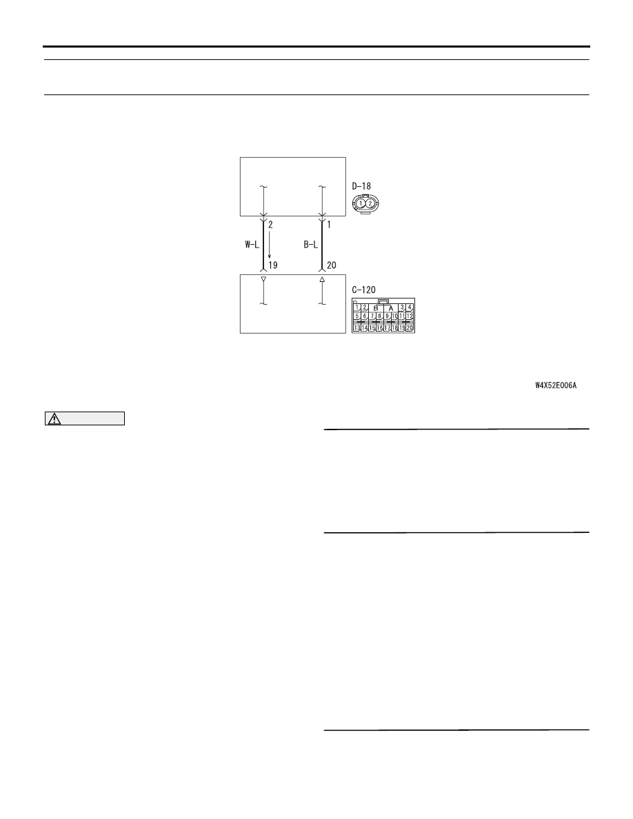
Wire colour code
B : Black     LG : Light green     G : Green     L : Blue     W : White     Y : Yellow     SB : Sky blue
BR : Brown     O : Orange     GR : Gray     R : Red     P : Pink     V : Violet

SIDE IMPACT 
SENSOR (FRONT: LH)

SRS-ECU

Side Impact Sensor (Front) (LH) Circuit

TROUBLESHOOTING

SUPPLEMENTAL RESTRAINT SYSTEM (SRS)

52B-93

impact sensor (RH).

(3) Connect the negative battery terminal.
(4) Erase diagnosis code from memory, and check 

the diagnosis code.

Q: Is diagnosis code B1428 or B1429 set?

YES : 

Replace the side impact sensor (LH) with a 

new one. (Refer to 

P.52B-236

). Go to Step 

5.

NO : 

Go to Step 4.

STEP 4. Check the harness wires for open circuit 
or short circuit between SRS-ECU connector 
C-120 (terminal No.19 and 20) and side impact 
sensor (LH) connector D-18 (terminal No.1 and 
2).

Q: Are the harness wires between SRS-ECU 

connector C-120 (terminal No.19 and 20) and side 

impact sensor (LH) connector D-18 (terminal No.1 
and 2) in good condition? 

YES : 

Go to Step 5.

NO : 

Repair the harness wires between 
SRS-ECU connector C-120 (terminal No.19 
and 20) and side impact sensor (LH) 
connector D-18 (terminal No.1 and 2).

STEP 5. Check whether the diagnosis code is 
reset.

Q: Is diagnosis code B1438 or B1439 set?

YES : 

Replace the SRS-ECU (Refer to 

P.52B-223

).

NO : 

An intermittent malfunction is suspected 
(Refer to GROUP 00, How to Use 
Troubleshooting/Inspection Service Points 

P.00-5

).

AC311438 AE

C-120 (Y)

Connector: C-120

Harness side
(front view)

AC302579AC

D-18 (Y)

Connector: D-18

Centre
pillar

Front vehicle

Harness side
(front view)

TROUBLESHOOTING

SUPPLEMENTAL RESTRAINT SYSTEM (SRS)

52B-94

Code No.B1440: Curtain air bag module (squib) (RH) system (short-circuited between terminals of the 
squib circuit) 

CAUTION

If diagnosis code B1440 is set in the SRS-ECU, 
always diagnose the CAN bus lines.

OPERATION

The SRS-ECU judges how severe a collision is by 
detecting signals from the side impact sensors and 
the side-airbag safing G-sensor. If the impact is over 
a predetermined level, the SRS-ECU outputs an 
ignition signal. At this time, if the side air bag safing 
G-sensor is on, the curtain air bag module will 
deploy. 

DIAGNOSIS CODE SET CONDITIONS

This diagnosis code is set if one curtain air bag 
module squib (RH) wire shorted to the other. 
However, if no diagnosis code resets, the SRS 
warning lamp will be switched off (diagnosis code will 
be retained).

PROBABLE CAUSES

• Improper engaged connector or defective short 

spring*

• Short circuit between the curtain air bag module 

(squib) (RH) circuit terminals

• Damaged connector(s)

• Malfunction of the SRS-ECU

NOTE: *: The squib circuit connectors integrate a 
"short" spring (which prevents the air bag from 
deploying unintentionally due to static electricity by 
shorting the positive wire to the earth wire in the 
squib circuit when the connectors are disconnected). 
Therefore, if connector C-118 or G-04 is damaged or 
improperly engaged, the short spring may not be 
released when the connector is connected.

DIAGNOSIS PROCEDURE

STEP 1. MUT-III CAN bus diagnostics

Use the MUT-III to diagnose the CAN bus lines.

Q: Is the check result normal?

YES : 

Go to Step 2

NO : 

Repair the CAN bus lines (Refer to GROUP 
54D, Diagnosis

P.54D-16

).

STEP 2. Check whether the diagnosis code is 
reset.

Check again if the diagnosis code is set.
(1) Erase the diagnosis code.

Wire colour code
B : Black     LG : Light green     G : Green     L : Blue     W : White     Y : Yellow     SB : Sky blue
BR : Brown     O : Orange     GR : Gray     R : Red     P : Pink     V : Violet

SRS-ECU

CONNECTOR
LOCK SWITCH

CONNECTOR
LOCK SWITCH

: CONNECTOR
  CONNECTED: ON
  CONNECTOR
  DISCONNECTED: OFF

NOTE

CURTAIN AIR BAG
MODULE
(SQUIB) (RH)

Curtain Air Bag Module (Squib) (RH) Circuit

TROUBLESHOOTING

SUPPLEMENTAL RESTRAINT SYSTEM (SRS)

52B-95

(2) Ignition: LOCK (OFF) position to ON
(3) On completion, check that the diagnosis code is 

not reset.

Q: Is the diagnosis code set?

YES : 

Go to Step 3 .

NO : 

There is an intermittent malfunction such as 
poor engaged connector(s) or open circuit 
(Refer to GROUP 00, How to Cope with 
Intermittent Malfunction 

P.00-5

).

STEP 3. MUT-III diagnosis code

CAUTION

To prevent damage to MUT-II/III, always turn the 
ignition switch to the "LOCK" (OFF) position 
before connecting or disconnecting MUT-II/III.
(1) Turn the ignition switch to the "ON" position.
(2) Check if the diagnosis code is set.
(3) Turn the ignition switch to the "LOOK" (OFF) 

position.

Q: Is diagnosis code B1519 set?

YES : 

Go to Step 4.

NO : 

Go to Step 5.

STEP 4. Connector lock check: SRS-ECU 
connector C-118 (MUT-III diagnosis code)
(1) Disconnect the negative battery terminal.

(2) Disconnect connectors C-118, and then 

reconnect them.

(3) Connect the negative battery terminal.
(4) Erase the diagnosis code memory, and check the 

diagnosis code.

Q: Is diagnosis code B1440 set?

YES : 

Go to Step 6.

NO : 

The procedure is complete. It is assumed 
that diagnosis code B1440 set as connector 
C-118 was engaged improperly.

STEP 5. Connector lock check: SRS-ECU 
connector C-118 and curtain air bag module (RH) 
connector G-04 (MUT-III diagnosis code)
(1) Disconnect the negative battery terminal.

(2) Disconnect connectors C-118 and G-04, and then 

reconnect them. For connector G-04, use a 
flat-tipped screwdriver to pull out the locking 
button at the harness side connector, and then 
disconnect the connector.

(3) Connect the negative battery terminal.
(4) Erase the diagnosis code memory, and check the 

diagnosis code.

Q: Is diagnosis code B1440 set?

YES : 

Go to Step 6.

NO : 

The procedure is complete. It is assumed 
that diagnosis code B1440 set as connector 
C-118 or G-04 was engaged improperly.

AC311438 AC

C-118 (Y)

Connector: C-118

Harness side
(front view)

AC311438 AC

C-118 (Y)

Connector: C-118

Harness side
(front view)

AC302575AD

 G-04 (B)

Connector: G-04

Harness side
(front view)

Roof centre duct

AC208384AM

G-04
Curtain air bag
module connector 

Flat-tip screw
driver

Locking button

G-04
Harness side
connector


Content   ..  1008  1009  1010  1011   ..