Mitsubishi Grandis. Manual - part 1006


  Index      Mitsubishi     Mitsubishi Grandis - service repair manual


Search            


Content   ..  1004  1005  1006  1007   ..


Mitsubishi Grandis. Manual - part 1006


TROUBLESHOOTING

SUPPLEMENTAL RESTRAINT SYSTEM (SRS)

52B-76

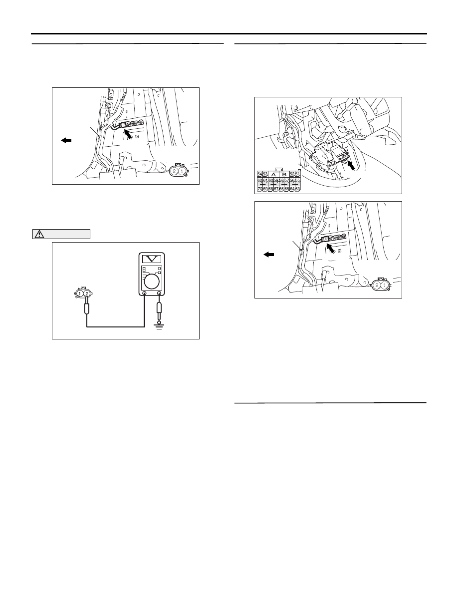
STEP 3. Check the side impact sensor (RH) 
power supply circuit. Voltage measurement at the 
side impact sensor (RH) connector D-01.
(1) Disconnect the negative battery terminal.

(2) Disconnect side impact sensor (RH) connector 

D-01, and measure at the wiring harness side.

(3) Connect the negative battery terminal.
(4) Turn the ignition switch to the "ON" position.

CAUTION

Do not insert a test probe into the terminal from 
its front side directly, as the connector contact 
pressure may be weakened.
(5) Measure the voltage between D-01 harness side 

connector terminal 2 and body earth.

OK: 9 V or more

Q: Is the check result normal?

YES : 

Replace the side impact sensor (RH). 

(Refer to 

P.52B-236

). Then go to Step 5.

NO : 

Go to Step 4.

STEP 4. Check the harness wires for open circuit 
or short circuit between SRS-ECU connector 
C-118 (terminal No.63 and 64) and side impact 
sensor (RH) connector D-01 (terminal No.1 and 
2).

Q: Are the harness wires between SRS-ECU 

connector C-118 (terminal No.63 and 64) and side 
impact sensor (RH) connector D-01 (terminal No.1 
and 2) in good condition?

YES : 

Go to Step 5.

NO : 

Replace the harness wires between 
SRS-ECU connector C-118 (terminal No.63 
and 64) and side impact sensor (RH) 
connector D-01 (terminal No.1 and 2).

STEP 5. Check whether the diagnosis code is 
reset.

Q: Is diagnosis code B1427 set?

YES : 

Replace the SRS-ECU (Refer to 

P.52B-223

).

NO : 

An intermittent malfunction is suspected 
(Refer to GROUP 00, How to Use 
Troubleshooting/Inspection Service Points 

P.00-5

).

AC303164AC

D-01 (Y)

Connector: D-01

Centre
pillar

Front vehicle

Harness side
(front view)

AC313348

D-01 Harness side
connector
(rear view)

AB

AC311438 AC

C-118 (Y)

Connector: C-118

Harness side
(front view)

AC303164AC

D-01 (Y)

Connector: D-01

Centre
pillar

Front vehicle

Harness side
(front view)

TROUBLESHOOTING

SUPPLEMENTAL RESTRAINT SYSTEM (SRS)

52B-77

Code No.B1428: Side-Impact sensor (RH) (Squib) for Power Supply Circuit
Code No.B1429: Side-Impact sensor (RH) (Squib) for Communication System

CAUTION

If diagnosis code B1428 or B1429 is set in the 
SRS-ECU, always diagnose the CAN main bus 
line.

OPERATION

The side impact sensor includes an analogue G 
sensor and CPU, etc. The CPU monitors the 
analogue G sensor output signal. If the CPU judges 
that the side-airbags and curtain air bags should be 
deployed, it sends a fire signal to the SRS-ECU to 
deploy the side-airbags and curtain air bags. In 
addition, the CPU diagnoses the internal 
components of the side impact sensor. If a 
malfunction occurs, it requests the SRS-ECU to set a 
diagnosis code.

DIAGNOSIS CODE SET CONDITIONS

These diagnosis codes are set if communication 
between the side impact sensor (RH) and the 
SRS-ECU is not possible or communication is faulty.

PROBABLE CAUSES

• Damaged wiring harnesses or connectors

• Malfunction of the side impact sensor (RH)

• Malfunction of the SRS-ECU

DIAGNOSIS PROCEDURE

STEP 1. MUT-III CAN bus diagnostics

Use the MUT-III to diagnose the CAN bus lines.

Q: Is the check result normal?

YES : 

Go to Step 2.

NO : 

Repair the CAN bus line (Refer to GROUP 
54D, Diagnosis 

P.54D-16

).

STEP 2. Check whether the diagnosis code is 
reset.

Check again if the diagnosis code is set.
(1) Erase the diagnosis code.
(2) Ignition: LOCK (OFF) position to ON
(3) On completion, check that the diagnosis code is 

not reset.

Q: Is the diagnosis code set?

YES : 

Go to Step 3.

NO : 

There is an intermittent malfunction such as 
poor engaged connector(s) or open circuit 
(Refer to GROUP 00, How to Cope with 
Intermittent Malfunction 

P.00-5

).

STEP 3.Check the side impact sensor (RH). 
(MUT-III diagnosis code.)
(1) Disconnect the negative battery terminal.
(2) Replace the side impact sensor (RH) with the 

Wire colour code
B : Black     LG : Light green     G : Green     L : Blue     W : White     Y : Yellow     SB : Sky blue
BR : Brown     O : Orange     GR : Gray     R : Red     P : Pink     V : Violet

SIDE IMPACT 
SENSOR (FRONT: RH)

SRS-ECU

Side Impact Sensor (Front) (RH) Circuit

TROUBLESHOOTING

SUPPLEMENTAL RESTRAINT SYSTEM (SRS)

52B-78

side impact sensor (LH).

(3) Connect the negative battery terminal.
(4) Erase diagnosis code memory, and check the 

diagnosis code.

Q: Is diagnosis code B1438 or B1439 set?

YES : 

Replace the side impact sensor (RH) with a 

new one. (Refer to 

P.52B-236

). Then go to 

Step 5.

NO : 

Go to Step 4.

STEP 4. Check the harness wires for open circuit 
or short circuit between SRS-ECU connector 
C-118 (terminal No.63 and 64) and side impact 
sensor (RH) connector D-01 (terminal No.1 and 
2).

Q: Is the check result normal? 

YES : 

Go to Step 5.

NO : 

Repair the harness wires between 
SRS-ECU connector C-118 (terminal No.63 
and 64) and side impact sensor (RH) 
connector D-01 (terminal No.1 and 2).

STEP 5. Check whether the diagnosis code is 
reset.

Q: Is diagnosis code B1428 or B1429 set?

YES : 

Replace the SRS-ECU (Refer to 

P.52B-223

).

NO : 

An intermittent malfunction is suspected 
(Refer to GROUP 00, How to Use 
Troubleshooting/Inspection Service Points 

P.00-5

).

AC311438 AC

C-118 (Y)

Connector: C-118

Harness side
(front view)

AC303164AC

D-01 (Y)

Connector: D-01

Centre
pillar

Front vehicle

Harness side
(front view)

TROUBLESHOOTING

SUPPLEMENTAL RESTRAINT SYSTEM (SRS)

52B-79

Code No.B1430: Side-Airbag Module (LH) (Squib) System Fault 1 (Short Circuit between Terminals of 
the Squib Circuit)

CAUTION

If diagnosis code B1430 is set in the combination 
meter, always diagnose the CAN bus lines.

OPERATION

• The SRS-ECU judges how severe a collision is 

by detecting signals from the left and right side 
impact sensors. If the impact is over a 
predetermined level, the SRS-ECU sends an 
ignition signal. At this time, if the side-airbag 
safing G-sensor is on, the SRS side-airbag will 
inflate.

• The ignition signal is input to the side-airbag 

module to inflate the side-airbag.

DIAGNOSIS CODE SET CONDITIONS

This diagnosis code is set if there is abnormal 
resistance between the input terminals of the 
side-airbag module (LH) (squib).

PROBABLE CAUSES

• Improper engaged connector or defective short 

spring*

• Short circuit between the side-airbag module 

(LH) (squib) circuit terminals

• Damaged connector(s)

• Malfunction of the SRS-ECU

NOTE:  *: The squib circuit connectors integrate a 
"short" spring (which prevents the air bag from 
deploying unintentionally due to static electricity by 
shorting the positive wire to the earth wire in the 
squib circuit when the connectors are disconnected). 
(Refer to 

P.52B-5

). Therefore, if connector C-120 or 

D-22 is damaged or improperly engaged, the short 
spring may not be released when the connector is 
connected.

DIAGNOSIS PROCEDURE

STEP 1. MUT-III CAN bus diagnostics

Use the MUT-III to diagnose the CAN bus lines.

Q: Is the check result normal?

YES : 

Go to Step 2

NO : 

Repair the CAN bus lines (Refer to GROUP 
54D, Diagnosis-Can Bus Diagnostic Chart 

P.54D-16

).

Wire colour code
B : Black     LG : Light green     G : Green     L : Blue     W : White     Y : Yellow     SB : Sky blue
BR : Brown     O : Orange     GR : Gray     R : Red     P : Pink     V : Violet

SIDE AIR BAG
MODULE
(SQUIB) (LH)

SRS-ECU

CONNECTOR
LOCK SWITCH

CONNECTOR
LOCK SWITCH

: CONNECTOR 
  CONNECTED: ON
  CONNECTOR 
  DISCONNECTED: OFF

NOTE

Side-Airbag Module (LH) (Squib) Circuit


Content   ..  1004  1005  1006  1007   ..