Content .. 999 1000 1001 1002 ..
Mitsubishi Grandis. Manual - part 1001
TROUBLESHOOTING
SUPPLEMENTAL RESTRAINT SYSTEM (SRS)
52B-56
Code No.B1413 Passenger’s (Front) Air Bag Module (1st Squib) System Fault for Power Supply
Circuit (Short-Circuited to Power Supply)
Code No.B1493: Passenger’s (Front) Air Bag Module (2nd Squib) System Fault for Power Supply
Circuit (Short-Circuited to Power Supply)
CAUTION
If diagnosis code B1413 <1st squib> or B1493
<2nd squib> is set in the SRS-ECU, always
diagnose the CAN main bus line.
OPERATION
• The SRS-ECU judges how severe a collision is
by detecting signals from the front impact sensors
and the front air bag analogue G-sensor. If the
impact is over a predetermined level, the
SRS-ECU sends an ignition signal. At this time, if
the front air bag safing G-sensor is on, the SRS
air bag will inflate.
• The ignition signal is input to the air bag module
via the clock spring to inflate the air bag.
DIAGNOSIS CODE SET CONDITIONS
This diagnosis code is set if there is abnormal
resistance between the input terminals of the
passenger's air bag module (squib). However, if no
diagnosis code resets, the SRS warning lamp will be
switched off (diagnosis code will be retained).
PROBABLE CAUSES
• Damaged harness wires and connectors
• Short to the power supply in the passenger's air
bag module (squib) harness
• Malfunction of the SRS-ECU
DIAGNOSIS PROCEDURE
STEP 1. MUT-III CAN bus diagnostics
Use the MUT-III to diagnose the CAN bus lines.
Q: Is the check result normal?
YES :
Go to Step 2.
NO :
Repair the CAN bus line (Refer to GROUP
54D, Diagnosis
STEP 2. Recheck for diagnosis code.
Check again if the diagnosis code is set.
(1) Erase the diagnosis code.
(2) Ignition: LOCK (OFF) position to ON
(3) On completion, check that the diagnosis code is
not reset.
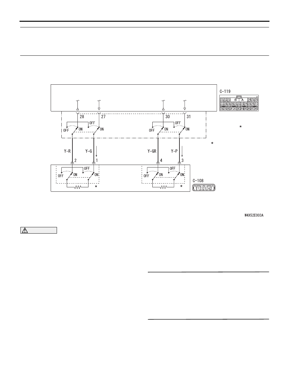
AIR BAG MODULE
(SQUIB)
(PASSENGER'S SIDE)
SRS-ECU
CONNECTOR
LOCK SWITCH
Wire colour code
B : Black LG : Light green G : Green L : Blue W : White Y : Yellow SB : Sky blue
BR : Brown O : Orange GR : Gray R : Red P : Pink V : Violet
: CONNECTOR
CONNECTED: ON
CONNECTOR
DISCONNECTED: OFF
NOTE
Passenger's (Front) Air Bag Module (1st Squib and 2nd Squib) Circuit