Mitsubishi Grandis. Manual - part 999


  Index      Mitsubishi     Mitsubishi Grandis - service repair manual


Search            


Content   ..  997  998  999  1000   ..


Mitsubishi Grandis. Manual - part 999


TROUBLESHOOTING

SUPPLEMENTAL RESTRAINT SYSTEM (SRS)

52B-48

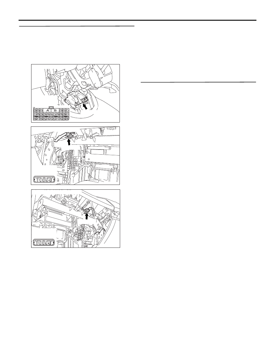
STEP 8. Check the harness for short circuit 
between SRS-ECU connector C-119 (terminal 
No.27 and 28 <1st squib> or terminal No.30 and 
31 <2nd squib>) and passenger's air bag module 
connector C-108 (terminal No.1 and 2 <1st squib> 
terminal No.4 and 3 <2nd squib>).

Q: Are harness wires between SRS-ECU connector 

C-119 (terminal No.27 and 28 <1st squib> or 

terminal No.30 and 31 <2nd squib>) and 
passenger's air bag module connector C-108 
(terminal No.1 and 2 <1st squib> terminal No.4 and 
3 <2nd squib>) in good condition?

YES : 

Go to Step 9.

NO : 

Replace the harness wires between 
SRS-ECU connector C-119 and 
passenger’s air bag module connector 
C-108. Then go to Step 9.

STEP 9. Check whether the diagnosis code is 
reset.

Q: Is diagnosis code B1410 <1st squib> or B1490 

<2nd squib> set?

YES : 

Return to Step 1.

NO : 

The procedure is complete.

AC311438 AD

C-119 (Y)

Connector: C-119

Harness side
(front view)

AC311373AC

C-108 (Y)

Connector: C-108 <LHD>

Harness side
(front view)

AC311375 AB

C-108 (Y)

Connector: C-108 <RHD>

Harness side
(front view)

TROUBLESHOOTING

SUPPLEMENTAL RESTRAINT SYSTEM (SRS)

52B-49

Code No.B1411: Passenger’s (Front) Air Bag Module (1st Squib) System Fault 2 (Open in the Squib 
Circuit)
Code No.B1491: Passenger’s (Front) Air Bag Module (2nd Squib) System Fault 2 (Open in the Squib 
Circuit)

CAUTION

If diagnosis code B1411 <1st squib> or B1491 
<2nd squib> is set in the SRS-ECU, always 
diagnose the CAN main bus line.

OPERATION

• The SRS-ECU judges how severe a collision is 

by detecting signals from the front impact sensors 
and the front air bag analogue G-sensor. If the 
impact is over a predetermined level, the 
SRS-ECU sends an ignition signal. At this time, if 
the front air bag safing G-sensor is on, the SRS 
air bag will inflate. 

• The ignition signal is input to the air bag module 

via the clock spring to inflate the air bag.

DIAGNOSIS CODE SET CONDITIONS

This diagnosis code is set if there is abnormal 
resistance between the input terminals of the 
passenger’s air bag module (squib). However, if no 
diagnosis code reset, the SRS warning lamp will be 
switched off (diagnosis code will be retained). 

PROBABLE CAUSES

• Open circuit in the passenger's air bag module 

(squib) circuit

• Improper connector contact

• Malfunction of the SRS-ECU

DIAGNOSIS PROCEDURE

STEP 1. MUT-III CAN bus diagnostics

Use the MUT-III to diagnose the CAN bus lines.

Q: Is the check result normal?

YES : 

Go to Step 2.

NO : 

Repair the CAN bus line (Refer to GROUP 
54D, Diagnosis 

P.54D-16

).

STEP 2. Check whether the diagnosis code is 
reset.

Check again if the diagnosis code is set.
(1) Erase the diagnosis code.
(2) Ignition: LOCK (OFF) position to ON
(3) On completion, check that the diagnosis code is 

AIR BAG MODULE 
(SQUIB) 
(PASSENGER'S SIDE)

SRS-ECU

CONNECTOR
LOCK SWITCH

Wire colour code
B : Black     LG : Light green     G : Green     L : Blue     W : White     Y : Yellow     SB : Sky blue
BR : Brown     O : Orange     GR : Gray     R : Red     P : Pink     V : Violet

: CONNECTOR
  CONNECTED: ON
  CONNECTOR
  DISCONNECTED: OFF

NOTE

Passenger's (Front) Air Bag Module (1st Squib and 2nd Squib) Circuit

TROUBLESHOOTING

SUPPLEMENTAL RESTRAINT SYSTEM (SRS)

52B-50

not reset.

Q: Is the diagnosis code set?

YES : 

Go to Step 3.

NO : 

There is an intermittent malfunction such as 
poor engaged connector(s) or open circuit 
(Refer to GROUP 00, How to Cope with 
Intermittent Malfunction 

P.00-5

).

STEP 3. Check the passenger's air bag module. 
(MUT-III diagnosis code.)
(1) Disconnect the negative battery terminal.

(2) Disconnect the passenger’s air bag module 

connector C-108.

(3) Slide the outer housing of the clock spring side of 

passenger’s air bag module connector C-108 in 
the arrow direction shown, and disconnect the 
connector.

(4) Connect special tool dummy resistor (MB991865) 

to special tool resistor harness (MB991866).

CAUTION

Do not insert a test probe into the terminal from 
its front side directly, as the connector contact 
pressure may be weakened.
(5) Insert special tool MB991866 into the harness 

side connector C-108 (terminal No.1 and 2 <1st 
squib> or terminal No.3 and 4 <2nd squib>) by 
backprobing.

(6) Connect the negative battery terminal.

CAUTION

Always diagnosis code B1491 is set when 
checking diagnosis code B1411. This is because 
the second side terminal is isolated when 
checking it, diagnosis code B1491 is set but this 
is not a fault. In addition, always diagnosis code 
B1411 is set when checking diagnosis code 
B1491 because the first side terminal is isolated. 
(7) Erase the diagnosis code memory, and check the 

diagnosis code.

Q: Is the checked diagnosis code set?

YES : 

Go to Step 4.

NO : 

Replace the passenger's air bag module. 
(Refer to 

P.52B-225

). Then go to Step 5.

AC311373AC

C-108 (Y)

Connector: C-108 <LHD>

Harness side
(front view)

AC311375 AB

C-108 (Y)

Connector: C-108 <RHD>

Harness side
(front view)

AC306561AI

Outer housing of the passenger's 
air bag module connector C-108

AC306760

AC306760AD

MB991865 (Dummy
resistor: 3 

Ω)

MB991866
(Resistor harness)

C-108 Harness
connector

C-108
Passenger's
air bag module
connector

TROUBLESHOOTING

SUPPLEMENTAL RESTRAINT SYSTEM (SRS)

52B-51

STEP 4. Resistance measurement between 
SRS-ECU connector C-119 (terminal No.27 and 28 
<1st squib> or terminal No.30 and 31 <2nd 
squib>) and the passenger's air bag module 
connector C-108 (terminal No.1 and 2 <1st squib> 
or terminal No.4 and 3 <2nd squib>).

(1) Disconnect SRS-ECU connector C-119 and 

passenger's air bag module connector C-108.

(2) Slide the outer housing of the clock spring side of 

passenger’s air bag module connector C-108 in 
the arrow direction shown, and disconnect the 
connector.

CAUTION

Do not insert a test probe into the terminal from 
its front side directly as the connector contact 
pressure may be weakened.
(3) Check for continuity between the following 

terminals.
<1st squib>

• SRS-ECU connector C-119 (terminal No.27) 

and the passenger’s air bag module 
connector C-108 (terminal No.1)

• SRS-ECU connector C-119 (terminal No.28) 

and the passenger’s air bag module 
connector C-108 (terminal No.2)

<2nd squib>

• SRS-ECU connector C-119 (terminal No.30) 

and the passenger’s air bag module 
connector C-108 (terminal No.3)

• SRS-ECU connector C-119 (terminal No.31) 

and the passenger’s air bag module 
connector C-108 (terminal No.4)

OK: Less than 2 

Q: Are the check results normal?

AC311438 AD

C-119 (Y)

Connector: C-119

Harness side
(front view)

AC311373AC

C-108 (Y)

Connector: C-108 <LHD>

Harness side
(front view)

AC311375 AB

C-108 (Y)

Connector: C-108 <RHD>

Harness side
(front view)

AC306561AI

Outer housing of the passenger's 
air bag module connector C-108

AC308151

42

31

38

27

21

41

28

39

22

30

25

47

36

33

44

34

45

37

48

26

29

23

40

32

43

35

46

24

B

A

C-119 
Harness side
connector
(rear view)

C-108
Harness side
connector
(rear view)

AD

<1st squib>

AC311099

42

31

38

27

21

41

28

39

22

30

25

47

36

33

44

34

45

37

48

26

29

23

40

32

43

35

46

24

B

A

C-119
Harness side
connector
(rear view)

C-108 
Harness side
connector
(rear view)

AC

<2nd squib>


Content   ..  997  998  999  1000   ..