Mitsubishi Grandis. Manual - part 50


  Index      Mitsubishi     Mitsubishi Grandis - service repair manual


Search            


Content   ..  48  49  50  51   ..


Mitsubishi Grandis. Manual - part 50


SYMPTOM PROCEDURES

SMART WIRING SYSTEM (SWS) NOT USING SWS MONITOR

54B-197

COMMENTS ON TROUBLE SYMPTOM

If the sunroof timer function does not work, the input 
circuit from the ignition switch (IG1) or the driver's 
door switch, the communication lines between the 
ETACS-ECU and the sunroof motor assembly 
(sunroof-ECU), the sunroof motor assembly 
(sunroof-ECU) or the ETACS-ECU may be defective.

POSSIBLE CAUSES

• Malfunction of ETACS-ECU

• Malfunction of the sunroof motor assembly 

(sunroof-ECU)

• Damaged harness wires and connectors

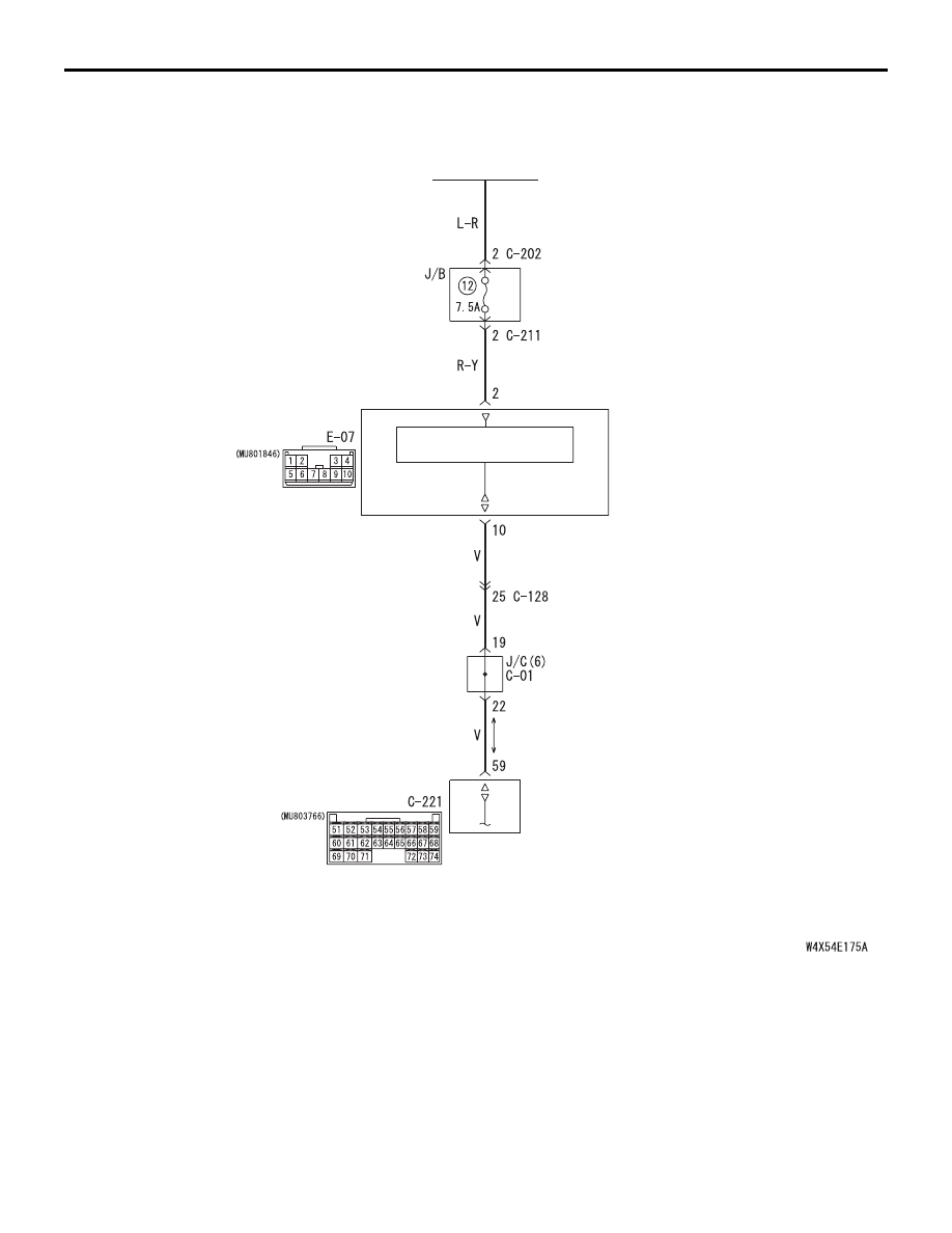
Sunroof Timer Function <RHD>

Wire colour code
B : Black     LG : Light green     G : Green     L : Blue     W : White     Y : Yellow     SB : Sky blue
BR : Brown     O : Orange     GR : Gray     R : Red     P : Pink     V : Violet

CONTROL CIRCUIT

IGNITION
SWITCH (IG2)

SUNROOF MOTOR
ASEEMBLY

ETACS-ECU

SYMPTOM PROCEDURES

SMART WIRING SYSTEM (SWS) NOT USING SWS MONITOR

54B-198

DIAGNOSTIC PROCEDURE

Step 1. Pulse check
Check the input signals from the ignition switch (IG1) 
and the driver's door switch.

OK: The MUT-III sounds or the voltmeter 
needle fluctuates.

Q: Are the check result normal?

All the signals are received normally. : 

Go to Step 

2.

The ignition switch (IG1) signal is not received. : 

Refer to inspection procedure Q-2 "The 
ignition switch (IG1) signal is not received 

P.54B-420

."

The driver’s door switch signal is not received. : 

Refer to inspection procedure Q-5 "The 
driver's door switch signal is not received 
<LH drive vehicles>

P.54B-434

   or <RH 

drive vehicles>

P.54B-436

 ."

Step 2. Connector check: E-07 sunroof motor 
assembly connector

Q: Is the check result normal?

YES : 

Go to Step 3.

NO : 

Repair the connector.

Step 3. Voltage measurement at the E-07 sunroof 
motor assembly connector.

(1) Disconnect the sunroof motor assembly 

connector, and measure at the harness side.

(2) Ignition switch: ON

(3) Check the voltage between E-07 sunroof motor 

assembly connector terminal No.2 and body 
earth.

OK: Battery positive voltage

Q: Is the check result normal?

YES : 

Go to Step 5.

NO : 

Go to Step 4.

System switch

Check conditions

Ignition switch (IG1)

When turned from ACC 
to ON

Driver’s door switch

When the driver’s door is 
opened

AC310651

Connector: E-07 <LHD>

AE

Harness side

AC310655

Connector: E-07 <RHD>

AF

Harness side

AC310651

Connector: E-07 <LHD>

AE

Harness side

AC310655

Connector: E-07 <RHD>

AF

Harness side

AC310507 CH

Connector E-07 
(harness side)

SYMPTOM PROCEDURES

SMART WIRING SYSTEM (SWS) NOT USING SWS MONITOR

54B-199

Step 4. Check the wiring harness between E-07 
sunroof motor assembly connector terminal No.2 
and the ignition switch (IG2).

NOTE: 

Prior to the wiring harness inspection, check junction 
block connectors C-211 and C-202, and repair if 
necessary.

• Check the power supply line for open circuit.

Q: Is the check result normal?

YES : 

The trouble can be an intermittent 

malfunction (Refer to GROUP 00 

− How to 

Cope with Intermittent Malfunction 

P.00-5

).

NO : 

Repair the wiring harness.

AC310651

Connector: E-07 <LHD>

AE

Harness side

AC310655

Connector: E-07 <RHD>

AF

Harness side

AC310624

Connectors: C-202, C-211

AV

<LHD>

Junction block (Front view)

C-211

C-202

C-202

C-211

Harness side

Harness side

4

6 5

3

2

1

3

1

2

AC310619

Connectors: C-202, C-211

AV

<RHD>

Junction block (Front view)

C-211

C-202

C-202

C-211

Harness side

Harness side

4

6 5

3

2

1

3

1

2

SYMPTOM PROCEDURES

SMART WIRING SYSTEM (SWS) NOT USING SWS MONITOR

54B-200

Step 5. Connector check: C-221 ETACS-ECU 
connector

Q: Is the check result normal?

YES : 

Go to Step 6.

NO : 

Repair the connector.

AC310626

Connector: C-221 <LHD>

AG

Junction block (rear view)

51

52

53

54

55

56

57

58

59

60

61

62

63

64

65

66

67

68

69

70

71

72

73

74

Harness side

C-221(GR)

AC310620

Connector: C-221 <RHD>

AF

Junction block (rear view)

51

52

53

54

55

56

57

58

59

60

61

62

63

64

65

66

67

68

69

70

71

72

73

74

Harness side

C-221(GR)


Content   ..  48  49  50  51   ..