Mitsubishi Grandis. Manual - part 37
SYMPTOM PROCEDURES
SMART WIRING SYSTEM (SWS) NOT USING SWS MONITOR
54B-145
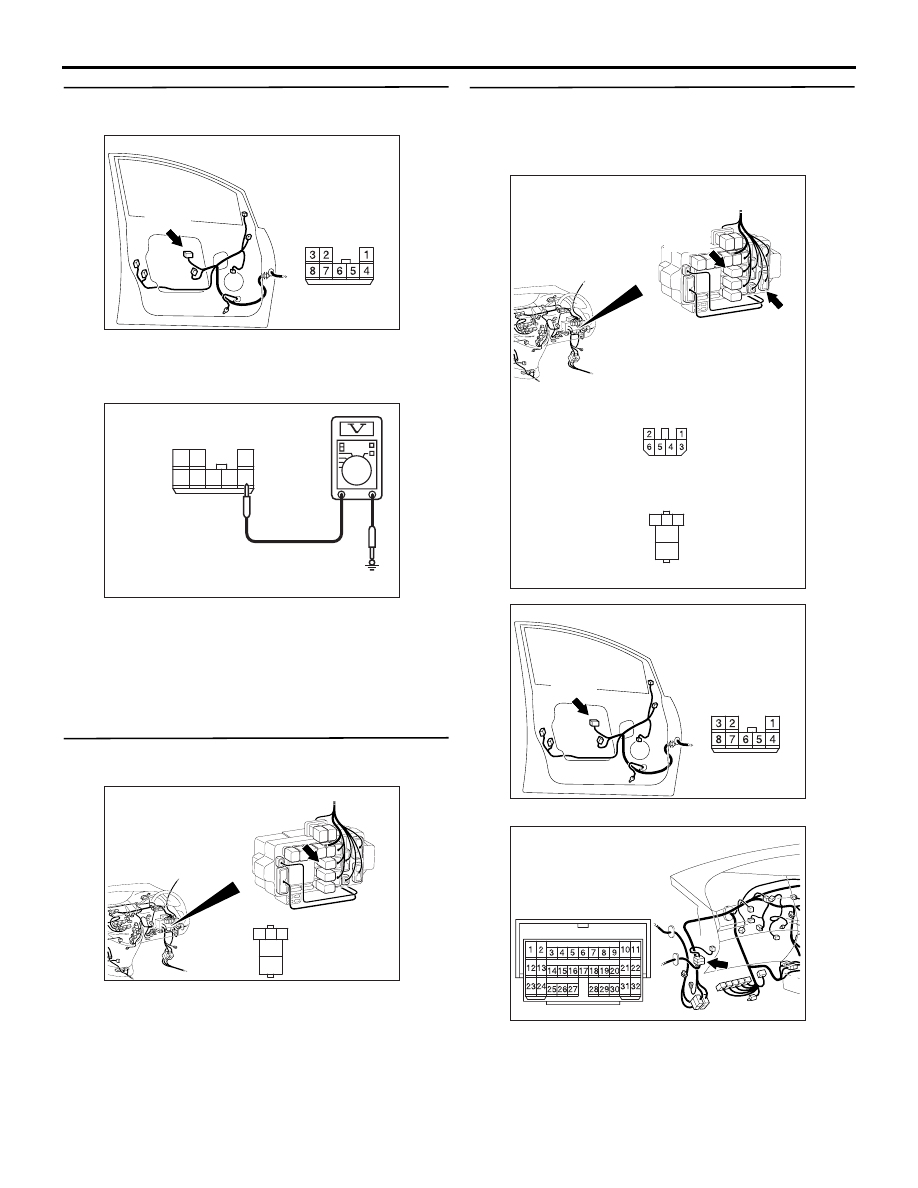
Step 15. Voltage measurement at F-26 power
window sub switch (front: LH) connector.
(1) Disconnect the connector, and measure at the
wiring harness side.
(2) Turn the ignition switch to the ON position.
(3) Voltage between terminal 4 and body earth
OK: System voltage
Q: Is the check result normal?
YES :
Go to Step 18.
NO :
Go to Step 16.
Step 16. Connector check: C-217 power window
relay connector
Q: Is the check result normal?
YES :
Go to Step 17.
NO :
Repair the connector.
Step 17. Check the wiring harness from F-26
power window sub switch (front: LH) connector
terminal No.4 to C-217 power window connector
terminal No.4.
NOTE:
Prior to the wiring harness inspection, check
intermediate connectors C-27 and junction block
connector C-202, and repair if necessary.
• Check the power supply line for open circuit.
Q: Is the check result normal?
AC310211
AB
Connector: F-26
Harness side
<RHD>
F-26(B)
1
4
5
3 2
7 6
8
AC301470
Connector F-26
(Harness Side)
AF
AC310618
Connector: C-217
3
4
5
1
2
Junction block side
<RHD>
Junction block (Front view)
AB
AC310619
Connector: C-202, C-217
AB
3
4
5
1
2
Junction block side
<RHD>
Junction block (Front view)
C-217
C-202
C-217
C-202
Harness side
AC310211
AB
Connector: F-26
Harness side
<RHD>
F-26(B)
AC310628AC
Connector: C-27 <RHD>