Mitsubishi Grandis. Manual - part 36
SYMPTOM PROCEDURES
SMART WIRING SYSTEM (SWS) NOT USING SWS MONITOR
54B-141
• Malfunction of the power window motor (front:
LH), power window motor (rear: RH) or power
window motor (rear: LH)
• Damaged harness wires and connectors
DIAGNOSIS PROCEDURE
Step 1. Check the power window main switch.
Check that the power window lock switch is turned
off.
Q: Is the check result normal?
YES :
Go to Step 2.
NO :
Turn off the power window lock switch.
Step 2. Determine a trouble spot.
Q: Which power window does not work?
Front passenger's door <LH drive vehicles> :
Go
to Step 3.
Front passenger's door <RH drive vehicles> :
Go
to Step 12.
Rear right door :
Go to Step 21.
Rear left door :
Go to Step 30.
Step 3. Connector check: F-15 power window sub
switch (front: RH) connector
Q: Is the check result normal?
YES :
Go to Step 4.
NO :
Repair the connector.
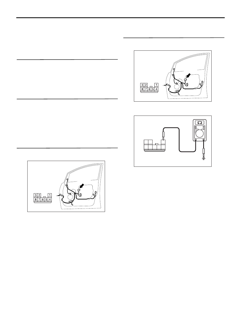
Step 4. Resistance measurement at F-15 power
window sub switch (front: RH) connector.
(1) Disconnect the connector, and measure at the
wiring harness side.
(2) Resistance between terminal 1 and body earth
OK: 2
Ω or less
Q: Is the check result normal?
YES :
Go to Step 6.
NO :
Go to Step 5.
AC311147
AB
Connector: F-15
<LHD>
Harness side
F-15(B)
AC311147
AB
Connector: F-15
<LHD>
Harness side
F-15(B)
1
4
5
3 2
7 6
8
AC301474
Connector F-15
(Harness side)
AE