Mitsubishi Grandis. Manual - part 22
 

  Index      Mitsubishi     Mitsubishi Grandis - service repair manual


Search            


Content   ..  20  21  22  23   ..


Mitsubishi Grandis. Manual - part 22


SYMPTOM PROCEDURES

SMART WIRING SYSTEM (SWS) NOT USING SWS MONITOR

54B-85

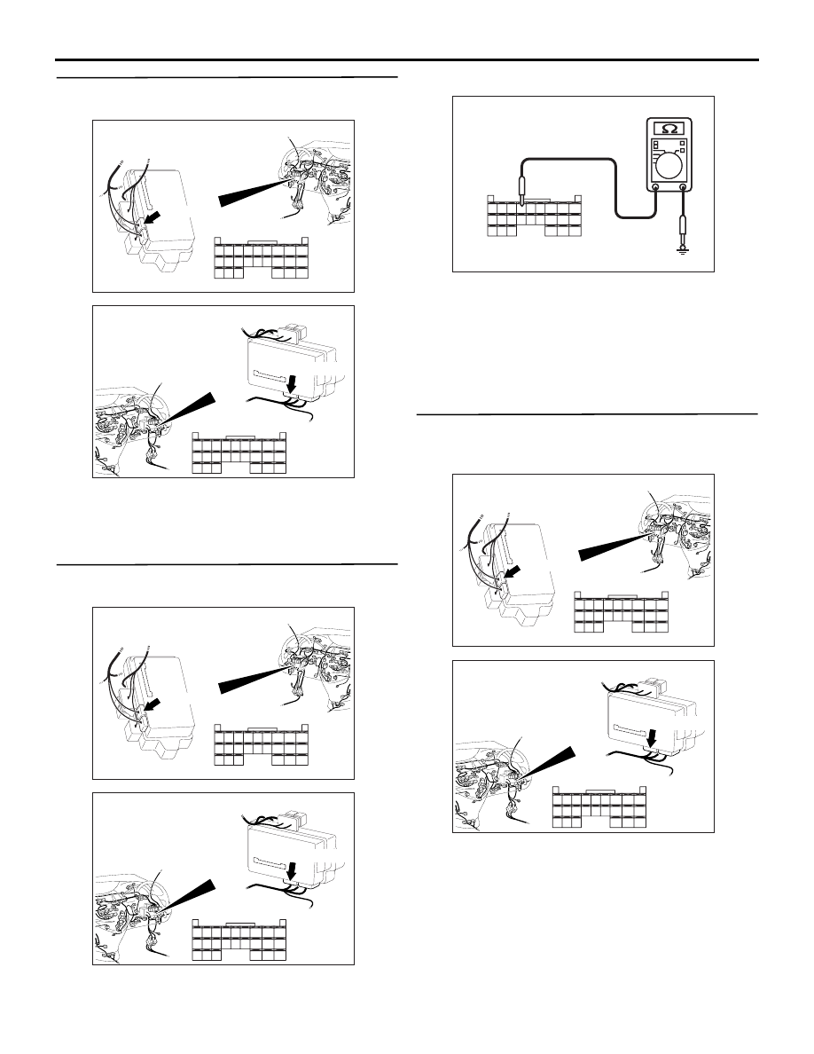
Step 3. Connector check: C-221 ETACS-ECU 
connector

Q: Is the check result normal?

YES : 

Go to Step 4.

NO : 

Repair the defective connector.

Step 4. Resistance measurement at the C-221 
ETACS-ECU connector.

(1) Disconnect the connector, and measure at the 

junction block side.

(2) Resistance between C-221 ETACS-ECU 

connector terminal No.56 and body earth

OK: 2 

 or less

Q: Is the check result normal?

YES : 

Go to Step 6.

NO : 

Go to Step 5.

Step 5. Check the wiring harness between C-221 
ETACS-ECU connector terminal No.56 and body 
earth.

• Check the earth wires for open circuit.

Q: Is the check result normal?

YES : 

The trouble can be an intermittent 

malfunction (Refer to GROUP 00 

− How to 

Cope with Intermittent Malfunction 

P.00-5

).

NO : 

Repair the wiring harness.

AC310626

Connector: C-221

Junction block (Rear view)

<LHD>

AC

51

52

53

54

55

56

57

58

59

60

61

62

63

64

65

66

67

68

69

70

71

72

73

74

Harness side

C-221(GR)

AC310620

Connector: C-221

Junction block 
(Rear view)

<RHD>

AC

51

52

53

54

55

56

57

58

59

60

61

62

63

64

65

66

67

68

69

70

71

72

73

74

Harness side

C-221(GR)

AC310506

51

52

53

54

55

56

57

58

59

60

61

62

63

64

65

66

67

68

69

70

71

72

73

74

AC310506DB

Connector C-221
(Harness side)

AC310626

Connector: C-221

Junction block (Rear view)

<LHD>

AC

51

52

53

54

55

56

57

58

59

60

61

62

63

64

65

66

67

68

69

70

71

72

73

74

Harness side

C-221(GR)

AC310620

Connector: C-221

Junction block 
(Rear view)

<RHD>

AC

51

52

53

54

55

56

57

58

59

60

61

62

63

64

65

66

67

68

69

70

71

72

73

74

Harness side

C-221(GR)

SYMPTOM PROCEDURES

SMART WIRING SYSTEM (SWS) NOT USING SWS MONITOR

54B-86

Step 6. Connector check: C-126 diagnosis 
connector

Q: Is the check result normal?

YES : 

Go to Step 7.

NO : 

Repair the defective connector.

Step 7. Check the wiring harness from C-221 
ETACS-ECU connector terminal Nos.51 and 67 to 
C-126 diagnosis connector terminal Nos.9 and 1.

• Check the communication lines for open circuit.

Q: Is the check result normal?

YES : 

Go to Step 8.

NO : 

Repair the wiring harness.

AC310613

AO

Connector: C-126 <LHD>

Harness side 
(Front side)

C-126 (B)

AC310631AK

Connector: C-126 <RHD>

C-126 (B)

Harness side 
(Front side)

AC310613

AO

Connector: C-126 <LHD>

Harness side 
(Front side)

C-126 (B)

AC310631AK

Connector: C-126 <RHD>

C-126 (B)

Harness side 
(Front side)

AC310626

Connector: C-221

Junction block (Rear view)

<LHD>

AC

51

52

53

54

55

56

57

58

59

60

61

62

63

64

65

66

67

68

69

70

71

72

73

74

Harness side

C-221(GR)

AC310620

Connector: C-221

Junction block 
(Rear view)

<RHD>

AC

51

52

53

54

55

56

57

58

59

60

61

62

63

64

65

66

67

68

69

70

71

72

73

74

Harness side

C-221(GR)

SYMPTOM PROCEDURES

SMART WIRING SYSTEM (SWS) NOT USING SWS MONITOR

54B-87

Step 8. Retest the system.

Check whether the communication with the MUT-III 
is possible.

Q: Is the check result normal?

YES : 

The trouble can be an intermittent 

malfunction (Refer to GROUP 00 

− How to 

Cope with Intermittent Malfunction 

P.00-5

).

NO : 

Replace the ETACS-ECU.

Inspection Procedure A-2: When the ignition switch is at the LOCK (OFF) position, the functions do 
not work normally. Check the battery power supply circuit to the ETACS-ECU.

CAUTION

Whenever the ECU is replaced, ensure that the 
power supply circuit and the earthing circuit are 
normal.

ETACS-ECS Power Supply Circuit <LHD>

26

FUSIBLE
LINK

ETACS-ECU

J/B SIDE

RELAY
BOX

Wire colour code
B : Black     LG : Light green
G : Green     L : Blue
W : White     Y : Yellow
SB : Sky blue     BR : Brown
O : Orange     GR : Gray
R : Red     P : Pink     V : Violet

SYMPTOM PROCEDURES

SMART WIRING SYSTEM (SWS) NOT USING SWS MONITOR

54B-88

COMMENTS ON TROUBLE SYMPTOM

If this circuit is defective and the ignition switch is at 
the LOCK (OFF) position, the ETACS-ECU does not 
work. In this case, the functions below will be 
suspended.

• Lamp reminder function

• Keyless entry system

• Ignition key cylinder illumination lamp

• Headlamp automatic-shutdown function

However, when the ignition switch is at the ON 
position, the functions below will work.

• Reading diagnosis code and checking input 

signal by MUT-III.

• Central door locking

• Headlamp and tail lamp

• Hazard warning lamp

• Interior lamps

POSSIBLE CAUSES

• Malfunction of the ETACS-ECU

• Damaged harness wires and connectors

ETACS-ECS Power Supply Circuit <RHD>

26

FUSIBLE
LINK

ETACS-ECU

J/B SIDE

RELAY
BOX

Wire colour code
B : Black     LG : Light green
G : Green     L : Blue
W : White     Y : Yellow
SB : Sky blue     BR : Brown
O : Orange     GR : Gray
R : Red     P : Pink     V : Violet


Content   ..  20  21  22  23   ..