Mitsubishi L200. Manual - part 831


  Index      Mitsubishi     Mitsubishi L200 - service repair manual 2012 year


Search            


Content   ..  829  830  831  832   ..


Mitsubishi L200. Manual - part 831


TROUBLESHOOTING

CONTROLLER AREA NETWORK (CAN)

54C-83

TROUBLE JUDGEMENT CONDITIONS
The M.U.T.-III judges the trouble when the periodi-
cally sent data from each ECU can be received nor-
mally but the resistance value between CAN_H and 
CAN_L line is other than from 50 

Ω to 70 Ω.

PROBABLE CAUSES

• Damaged harness wires and connectors

• Malfunction of the ETACS-ECU

• Malfunction of the engine-ECU

DIAGNOSIS PROCEDURE

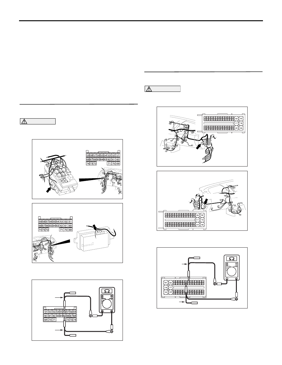
STEP 1. Resistance measurement at C-219 
ETACS-ECU connector.

CAUTION

A digital multimeter should be used. For details 
refer to 

P.54C-7

.

AC509934

Connector: C-219 <LHD>

AD

C-219 (GR)

Harness side

Junction block

AC509943

Connector: C-219 <RHD>

AB

C-219 (GR)

Harness side

Junction block
 (Rear view)

(1) Remove the ETACS-ECU, and measure at the 

equipment side.

AC204738

AC204738

AC204738HL

Equipment side: C-219

Test 
harness

Test 
harness

(2) Resistance at C-219 ETACS-ECU connector 

terminal Nos.56 and 65

OK: 120 

± 20 

Q: Is the check result normal?

YES : 

<Within 120 

± 20 Ω> Go to Step 2.

NO : 

<Not within 120 

± 20 Ω> Replace the 

ETACS-ECU.

STEP 2. Resistance measurement at C-103 
engine-ECU connector.

CAUTION

A digital multimeter should be used. For details 
refer to 

P.54C-7

.

AC903853

BV

Connector: C-103 <LHD>

C-103 (B)

Harness side

AC903865 AY

Connector: C-103 <RHD>

Harness side

C-103 (B)

(1) Remove the engine-ECU, and measure at the 

equipment side.

AC204738SK

Equipment side: C-103

Test 
harness

Test 
harness

(2) Resistance between C-103 engine-ECU 

TROUBLESHOOTING

CONTROLLER AREA NETWORK (CAN)

54C-84

connector terminal Nos.108 and 109

OK: 120 

± 20 

CAUTION

Strictly observe the specified wiring harness 
repair procedure. For details refer to 

P.54C-7

.

Q: Is the check result normal?

YES : 

<Within 120 

± 20 Ω> Repair the wiring 

harness between the ETACS-ECU 
connector and the engine-ECU connector.

NO : 

<Not within 120 

± 20 Ω> Replace the 

engine-ECU.

TROUBLESHOOTING

CONTROLLER AREA NETWORK (CAN)

54C-85

Diagnosis Item 5: Diagnose when the M.U.T.-III cannot receive the data sent by ETACS-ECU.

CAUTION

When servicing a CAN bus line, earth yourself by touching a metal object such as an unpainted water 
pipe. If you fail to do, a component connected to the CAN bus line may be broken.

Wire colour code 
B : Black     LG : Light green     G : Green     L : Blue     W : White 
Y : Yellow     SB : Sky blue     BR : Brown     O : Orange     GR : Grey 
R : Red     P : Pink     V : Violet     PU : Purple     SI : Silver

A/T-ECU

DIAGNOSIS 
CONNECTOR

ENGINE-ECU

STEERING 
WHEEL 
SENSOR

G AND 
YAW RATE 
SENSOR

A/C-ECU

ABS-ECU

ASTC-ECU

ETACS-ECU

RV METER

NOTE

:VEHICLES WITH ABS
:VEHICLES WITH ASTC
:VEHICLES WITH RV METER
:VEHICLES WITH AUTOMATIC-A/C
:LHD
:RHD
:A/T

TROUBLESHOOTING

CONTROLLER AREA NETWORK (CAN)

54C-86

FUNCTION
The diagnostic result demonstrates that "the M.U.T.-
III cannot receive the sent data from the ETACS-
ECU" when the M.U.T.-III checks the periodically 
sent data from each ECU.

TROUBLE JUDGEMENT CONDITIONS
M.U.T.-III judges the trouble when the periodically 
sent data from ETACS-ECU cannot be received. 


Content   ..  829  830  831  832   ..