Mitsubishi L200. Manual - part 830


  Index      Mitsubishi     Mitsubishi L200 - service repair manual 2012 year


Search            


Content   ..  828  829  830  831   ..


Mitsubishi L200. Manual - part 830


TROUBLESHOOTING

CONTROLLER AREA NETWORK (CAN)

54C-79

equipment side.

AC204738

AC204738

AC204738

AC204738

AC204738MO

Test 
harness

Test 
harness

Equipment side: C-43

(2) Resistance at C-43 A/C-ECU connector terminal 

Nos.6 and 7

OK: 1 k

 or more

Q: Is the check result normal?

YES : 

<1 k

Ω or more> Repair the wiring harness 

between joint connector (CAN1) and the A/
C-ECU connector.

NO : 

<Less than 1 k

Ω> Check the A/C-ECU 

connector, and repair if necessary. If the A/
C-ECU connector is in good condition, 
replace the A/C-ECU.

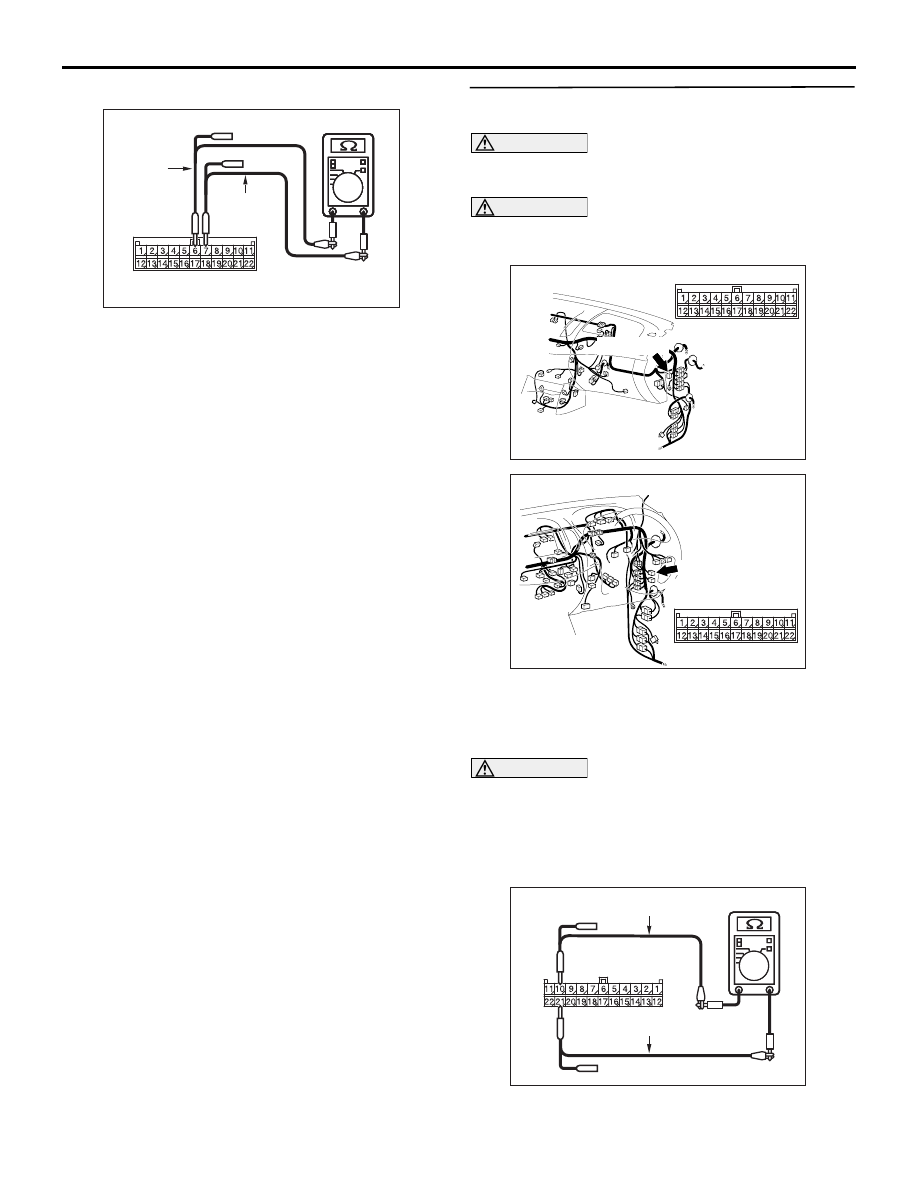
STEP 23. Resistance measurement at C-119 joint 
connector (CAN1).

CAUTION

A digital multimeter should be used. For details 
refer to 

P.54C-7

.

CAUTION

The test wiring harness should be used. For 
details refer to 

P.54C-7

.

AC903853

BM

Connector: C-119 <LHD>

C-119 (GR)

AC903868

CM

Connector: C-119 <RHD>

C-119 (GR)

(1) Disconnect the joint connector (CAN1), and 

measure at the wiring harness side.

(2) Turn the ignition switch to the LOCK (OFF) 

position.

CAUTION

When measuring the resistance, disconnect the 
negative battery terminal. For details refer to 

P.54C-7

.

(3) Ensure that the negative battery terminal is 

disconnected.

AC204738

AC204738PI

Harness side: C-119

Test harness

Test harness

(4) Resistance between C-119 joint connector 

TROUBLESHOOTING

CONTROLLER AREA NETWORK (CAN)

54C-80

(CAN1) terminal Nos.10 and 21

OK: 1 k

 or more

CAUTION

Strictly observe the specified wiring harness 
repair procedure. For details refer to 

P.54C-7

.

Q: Is the check result normal?

YES : 

<1 k

Ω or more> Repair the wiring harness 

between joint connector (CAN1) and the 
intermediate connector C-53.

NO : 

<Less than 1 k

Ω> Check the diagnosis 

connector, and repair if necessary. If the 
diagnosis connector is in good condition, 
repair the wiring harness between joint 
connector (CAN1) and the diagnosis 
connector.

TROUBLESHOOTING

CONTROLLER AREA NETWORK (CAN)

54C-81

Diagnosis Item 4: Diagnose the terminator resistors

CAUTION

When servicing a CAN bus line, earth yourself by touching a metal object such as an unpainted water 
pipe. If you fail to do, a component connected to the CAN bus line may be broken.

Wire colour code 
B : Black     LG : Light green     G : Green     L : Blue     W : White 
Y : Yellow     SB : Sky blue     BR : Brown     O : Orange     GR : Grey 
R : Red     P : Pink     V : Violet     PU : Purple     SI : Silver

A/T-ECU

DIAGNOSIS 
CONNECTOR

ENGINE-ECU

STEERING 
WHEEL 
SENSOR

G AND 
YAW RATE 
SENSOR

A/C-ECU

ABS-ECU

ASTC-ECU

ETACS-ECU

RV METER

NOTE

:VEHICLES WITH ABS
:VEHICLES WITH ASTC
:VEHICLES WITH RV METER
:VEHICLES WITH AUTOMATIC-A/C
:LHD
:RHD
:A/T

TROUBLESHOOTING

CONTROLLER AREA NETWORK (CAN)

54C-82

FUNCTION
The resistance in the communication errors condition 
cannot be measured by the CAN bus diagnostics, 
therefore, judge the terminator resistor only when 
receiving the each ECU periodically sent data nor-

mally.


Content   ..  828  829  830  831   ..