Mitsubishi L200. Manual - part 820
TROUBLESHOOTING
CONTROLLER AREA NETWORK (CAN)
54C-39
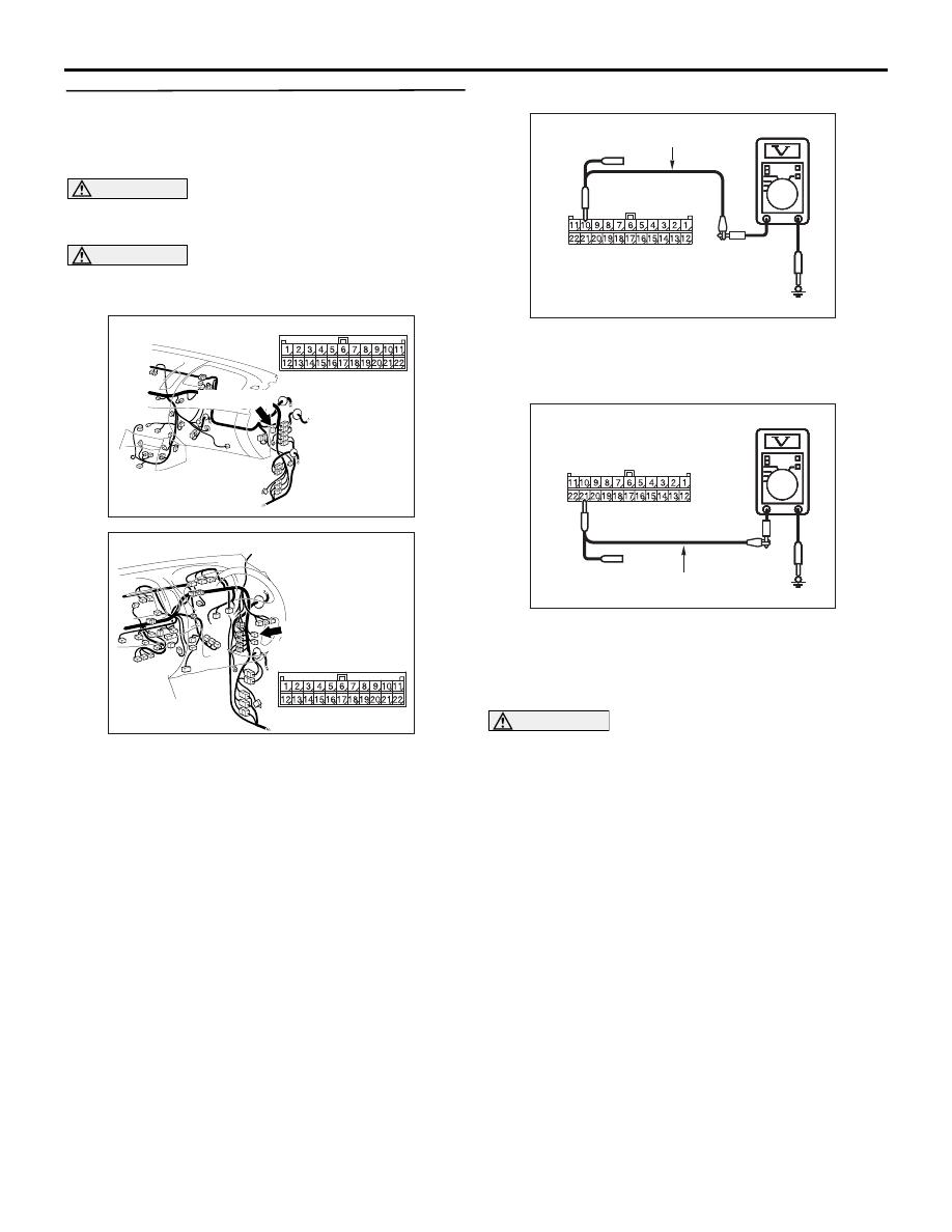
STEP 22. Check the CAN line between joint
connector (CAN1) and the diagnosis connector.
Voltage measurement at C-119 joint connector
(CAN1).
CAUTION
A digital multimeter should be used. For details
refer to
CAUTION
The test wiring harness should be used. For
details refer to
AC903853
BM
Connector: C-119 <LHD>
C-119 (GR)
AC903868
CM
Connector: C-119 <RHD>
C-119 (GR)
(1) Disconnect joint connector (CAN1), and measure
at the wiring harness side.
(2) Connect the negative battery terminal, and turn
the ignition switch to the ON position.
AC209365
AC209365
AC209365
AC209365
AC209365SA
Harness side: C-119
Test harness
(3) Voltage between C-119 joint connector (CAN1)
terminal No.10 (CAN_H) and body earth
OK: Less than 1.0 V
AC209365
AC209365
AC209365
Test harness
AC209365
AC209365
AC209365SB
Harness side: C-119
(4) Voltage between C-119 joint connector (CAN1)
terminal No.21 (CAN_L) and body earth
OK: Less than 1.0 V
(5) Disconnect the negative battery terminal.
CAUTION
Strictly observe the specified wiring harness
repair procedure. For details refer to
Q: Is the check result normal?
YES :
<Less than 1.0 V> Repair the intermediate
connector, or the wiring harness between
joint connector (CAN1) and the intermediate
connector C-53 <LHD> or C-35 <RHD>.
NO :
<1.0 V or more> Repair the diagnosis
connector, or the wiring harness between
joint connector (CAN1) and the diagnosis
connector.