Mitsubishi L200. Manual - part 819
TROUBLESHOOTING
CONTROLLER AREA NETWORK (CAN)
54C-35
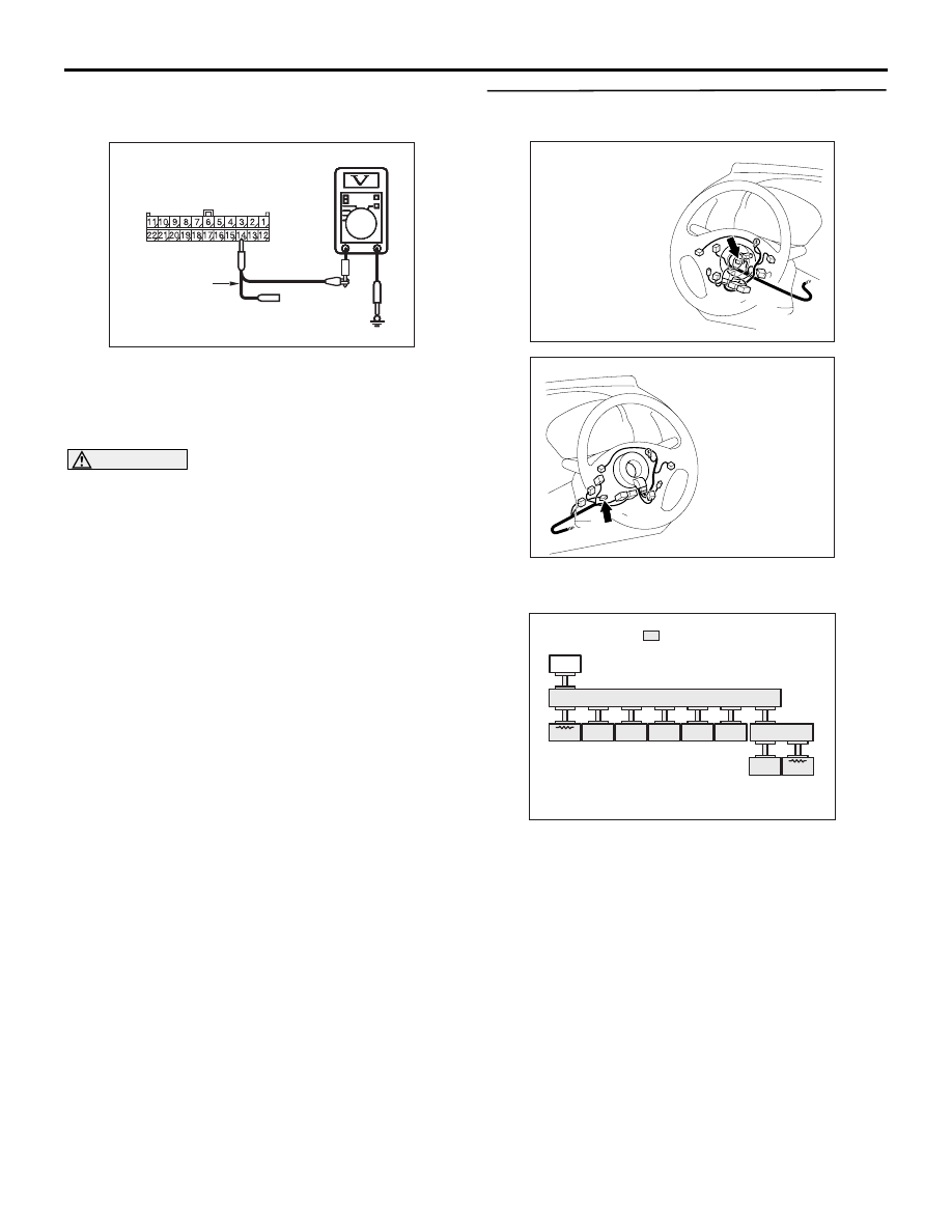
terminal No.3 (CAN_H) and body earth
OK: 4.0 V or less
AC209365
AC209365
AC209365
Test
harness
AC209365
AC209365
AC209365RV
Harness side: C-119
(4) Voltage between C-119 joint connector (CAN1)
terminal No.14 (CAN_L) and body earth
OK: 4.0 V or less
(5) Disconnect the negative battery terminal.
CAUTION
Strictly observe the specified wiring harness
repair procedure. For details refer to
Q: Is the check result normal?
YES :
<4.0 V or less> Go to Step 18.
NO :
<More than 4.0 V> Go to Step 17.
STEP 17. M.U.T.-III CAN bus diagnostics [steering
wheel sensor connector disconnected]
AC903858
Connector: C-308 <LHD>
AK
AC903869
Connector: C-308 <RHD>
AK
(1) Disconnect steering wheel sensor connector C-
308, and diagnose by using the M.U.T.-III.
ACA01247
: Red section on screen
AB
ETACS
DISPLAY
ABS/ASC
SAS
YR/G
A/C
AT
ENGINE
JC
JC
M.U.T.
(2) Diagnose CAN bus lines, and check if M.U.T.-III
screen is as shown in the illustration.
Q: Does M.U.T.-III screen correspond to the
illustration?
YES :
Repair the wiring harness between joint
connector (CAN1) and the steering wheel
sensor connector.
NO :
Check the steering wheel sensor connector,
and repair if necessary. If the steering wheel
sensor connector is in good condition, repair
the steering wheel sensor power supply
circuit.