Mitsubishi L200. Manual - part 799


  Index      Mitsubishi     Mitsubishi L200 - service repair manual 2012 year


Search            


Content   ..  797  798  799  800   ..


Mitsubishi L200. Manual - part 799


DIAGNOSIS CODE PROCEDURES

LOCAL INTERCONNECT NETWORK (LIN)

54B-7

DIAGNOSIS PROCEDURE

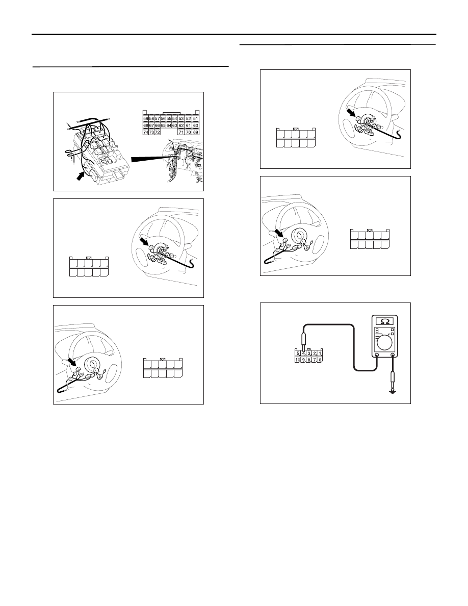
STEP 1. Connector check: C-219 ETACS-ECU 
connector, C-302 column switch connector

AC509934

Connector: C-219 <LHD>

AD

C-219 (GR)

Harness side

Junction block

AC509945AB

Harness side

Connector: C-302 <LHD>

10

5

6

7

9 8

3

4

2 1

AC509946AB

Harness side

Connector: C-302 <RHD>

10

5

6

7

9 8

3

4

2 1

Q: Is the check result normal?

YES : 

Go to Step 2.

NO : 

Repair the defective connector. Go to Step 
7.

STEP 2. Resistance measurement at the C-302 
column switch connector

AC509945AB

Harness side

Connector: C-302 <LHD>

10

5

6

7

9 8

3

4

2 1

AC509946AB

Harness side

Connector: C-302 <RHD>

10

5

6

7

9 8

3

4

2 1

(1) Disconnect the connector, and measure at the 

wiring harness side.

AC310506KM

Connector C-302 
(Harness side)

(2) Measure the resistance between the C-302 

column switch connector terminal No. 4 and the 
body earth.

OK: Continuity exists (2 

 or less)

Q: Is the check result normal?

YES : 

Go to Step 4.

NO : 

Go to Step 3.

DIAGNOSIS CODE PROCEDURES

LOCAL INTERCONNECT NETWORK (LIN)

54B-8

STEP 3. Check the wiring harness between C-302 
column switch connector terminal No. 4 to body 
earth

AC509945AB

Harness side

Connector: C-302 <LHD>

10

5

6

7

9 8

3

4

2 1

AC509946AB

Harness side

Connector: C-302 <RHD>

10

5

6

7

9 8

3

4

2 1

Check the earth wires for open circuit.

Q: Is the check result normal?

YES : 

The trouble can be an intermittent 

malfunction (Refer to GROUP 00 

− How to 

use Troubleshooting/inspection Service 
Points 

− How to Cope with Intermittent 

Malfunction ).

NO : 

Repair the wiring harness.

STEP 4. Voltage measurement at the C-302 
column switch connector.

AC509945AB

Harness side

Connector: C-302 <LHD>

10

5

6

7

9 8

3

4

2 1

AC509946AB

Harness side

Connector: C-302 <RHD>

10

5

6

7

9 8

3

4

2 1

(1) Disconnect the connector, and measure at the 

wiring harness side.

AC310507MD

Connector C-302 
(Harness side)

(2) Measure the voltage between the C-302 column 

switch connector terminal No. 1 and the body 
earth.

OK: System voltage

Q: Is the check result normal?

YES : 

Go to Step 6.

NO : 

Go to Step 5.

DIAGNOSIS CODE PROCEDURES

LOCAL INTERCONNECT NETWORK (LIN)

54B-9

STEP 5. Check the wiring harness between C-302 
column switch connector terminal No. 1 and the 
C-209 junction block connector terminal No. 2

AC509934

Connector: C-209 <LHD>

Junction block (Front view)

CT

Harness side

AC509945AB

Harness side

Connector: C-302 <LHD>

10

5

6

7

9 8

3

4

2 1

AC509946AB

Harness side

Connector: C-302 <RHD>

10

5

6

7

9 8

3

4

2 1

Check the power supply line for open circuit and 
short circuit.
NOTE: 

AC903853

Connector: C-132 <LHD>

AB

C-132 (GR)

AC903865

Connector: C-132 <RHD>

AB

C-132 (GR)

Prior to the wiring harness inspection, check joint 
connector C-132, and repair if necessary.

Q: Is the check result normal?

YES : 

The trouble can be an intermittent 

malfunction (Refer to GROUP 00 

− How to 

use Troubleshooting/inspection Service 
Points 

− How to Cope with Intermittent 

Malfunction ).

NO : 

Repair the wiring harness.

DIAGNOSIS CODE PROCEDURES

LOCAL INTERCONNECT NETWORK (LIN)

54B-10

STEP 6. Check the wiring harness between C-219 
ETACS-ECU connector terminal No.54 and C-302 
column switch connector terminal No.3.

AC509934

Connector: C-219 <LHD>

AD

C-219 (GR)

Harness side

Junction block

AC509945AB

Harness side

Connector: C-302 <LHD>

10

5

6

7

9 8

3

4

2 1

AC509946AB

Harness side

Connector: C-302 <RHD>

10

5

6

7

9 8

3

4

2 1

Check the communication line for open circuit.

Q: Is the check result normal?

YES : 

Go to Step 7.

NO : 

Repair the wiring harness. Go to Step 7.

STEP 7. Check whether the diagnosis code is 
reset.
Check again if the diagnosis code is set to the 
ETACS-ECU.
(1) Erase the diagnosis code.
(2) Turn the ignition switch from "LOCK" (OFF) 

position to "ON" position.

(3) On completion, check that the diagnosis code is 

reset.

Q: Is the diagnosis code set?

YES : 

Replace the lighting switch.

NO : 

A poor connection, open circuit or other 
intermittent malfunction is present in the LIN 
bus lines between the column-ECU and the 
ETACS-ECU (Refer to GROUP 00, How to 
Use Troubleshooting/Inspection Service 
Points 

− How to Cope with Intermittent 

Malfunctions ).

Code No.U1504: Lighting control sensor LIN timeout <Vehicles with auto lamp>

NOTE: When the diagnosis codes relating to the LIN 
communication error are set, make sure of the vehi-
cle equipment. When the vehicle is not equipped with 
the system the ETACS-ECU communicates to, the 
diagnosis code is always set. This is not abnormal.


Content   ..  797  798  799  800   ..