Mitsubishi L200. Manual - part 780


  Index      Mitsubishi     Mitsubishi L200 - service repair manual 2012 year


Search            


Content   ..  778  779  780  781   ..


Mitsubishi L200. Manual - part 780


RV METER

CHASSIS ELECTRICAL

54A-487

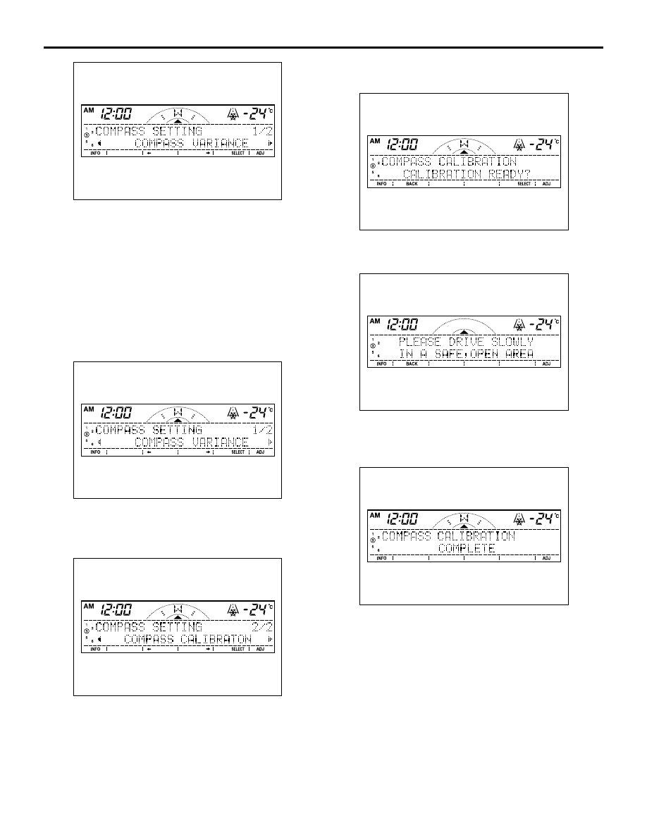
5. Press the [BACK] button to return to the 

"COMPASS VARIANCE" screen.

HOW TO SET THE COMPASS CALIBRA-
TION

NOTE: Perform compass calibration in a space 
where the vehicle can turn around, with the engine 
running.
The "COMPASS SETTING" screen is displayed with 

the user customisation function in the RV meter.

1. When the "COMPASS VARIANCE" screen is 

displayed, press the [SELECT] button.

2. Press the [

←] button or the [→] button.

3. When the "COMPASS CALIBRATION" screen is 

displayed, press the [SELECT] button.

4. When "CALIBRATION READY?" is indicated, 

press the [SELECT] button.

5. When "PLEASE DRIVE SLOWLY IN A SAFE, 

OPEN AREA" is indicated, turn the vehicle 360

° in 

a safe and open area.

6. "COMPASS CALIBRATION COMPLETE" is 

indicated with a blip, and the compass calibration 
is completed. When three seconds have elapsed 
after completion, the information screen is 
displayed.

AC900073

AC900073

AC900074

AC900075

AC900078

AC900079

RV METER

CHASSIS ELECTRICAL

54A-488

NOTE: 

.

When the engine is stopped during compass calibra-

tion, "PLEASE START ENGINE" is displayed. 
Perform compass calibration with the engine run-
ning.

If the compass sensor is not normal during compass 

calibration, "COMPASS SENSOR ERROR" is 
displayed. In this case, perform RV meter trouble-
shooting "The compass does not indicate nor-
mally". (Refer to 

P.54A-483

.)

VEHICLE MAGNETIC COMPENSATION

M1543009700288

DEMAGNETIZATION AND CORRECTION 
METHOD

CAUTION

• If the tip of demagnetizer touches the roof 

panel, the magnetising condition of body 
becomes worse to the contrary. Absolutely 
avoid this.

• If the demagnetizer is turned OFF near the 

body or it is suddenly separated from the 
body, the magnetising condition of body 
becomes worse to the contrary. Absolutely 
avoid these.

1. Turn the ignition switch to the OFF position.

2. Demagnetize the body using a commercial 

demagnetizer.

3. While keeping the distance between the tip of 

demagnetizer and the roof panel to approximately 
50 mm, move the demagnetizer slowly with a 
sweeping manner on the rear-half surface of roof 
panel.

4. Slowly draw the demagnetizer apart from the 

body. Turn OFF the switch of demagnetizer when 
it is apart from the body more than 50 mm. 

5. After demagnetization of the geomagnetism, 

perform a compass calibration (Refer to How to 
Set the Compass 

P.54A-486

).

AC900077

AC900076

AC001246AB

Commercial demagnetizer

AC900188

Front

Demagnetizer

Approximately 50 mm

Roof panel

AB

RV METER

CHASSIS ELECTRICAL

54A-489

RV METER

REMOVAL AND INSTALLATION

M1543014100077

CAUTION

• When the RV meter of another vehicle is replaced, perform "BODY TYPE" and "FUNCTION TYPE 

RESET" in the service mode. (Refer to 

P.54A-457

.)

• After replacement of the RV meter, when the ignition switch is turned to the "ON" position for the 

first time, "BODY TYPE" and "DESTINATION" of the service mode are displayed automatically. Set 
each item following the description of the service mode. (Refer to 

P.54A-457

.) Also perform the 

deviation angle correction. (Refer to 

P.54A-486

.)

AMBIENT AIR TEMPERATURE 
SENSOR

REMOVAL AND INSTALLATION

M1543032700042

INSPECTION

AMBIENT AIR TEMPERATURE SENSOR 
INSPECTION

M1546602600054

Check to see that the resistance shown in the graph 
is almost satisfied when measuring the resistance 
between the sensor terminals under two or more dif-
ferent temperature conditions.

AC900684

1

2

2

3

AB

Removal steps 

RV meter hood (Refer to GROUP 
52A 

− Instrument Panel Assembly 

)

1.

RV meter assembly

2.

RV meter bracket

3.

RV meter

AC501630

AC

1

Removal steps 

radiator grille (RH) (GROUP 51, 
Radiator grille .)

1.

Ambient air temperature sensor

AC209192AB

10

8

6

4

2

0

10

20

30

40

–10

0

RESISTANCE

(k )

TEMPERATURE (˚C)

DEFOGGER

CHASSIS ELECTRICAL

54A-490

DEFOGGER

TROUBLESHOOTING

M1540500200033

Refer to GROUP 55A, Troubleshooting .

INSPECTION

PRINTED HEATER LINES CHECK

M1540500500368

1. Run engine at 2,000 r/min. Check heater element 

with battery at full.

2. Turn "ON" rear window defogger switch. Measure 

heater element voltage with circuit tester at rear 
window glass centre A. Condition is good if it 
indicates about six volts.

3. If 12 volts is indicated at A, there is a break in the 

negative terminals from A. Move test bar slowly to 
negative terminal to detect where voltage 
changes suddenly (0 volts).

4. If 0 volts is indicated at A, there is a break in the 

positive terminals from A. Defect where the 
voltage changes suddenly (12 volts) in the same 
method described above.

5. If a malfunction such as open circuit occurs, 

replace the rear window glass <vehicles without 
rear panel power window> or rear slide window 
glass <vehicles with rear panel power window>. 
(Refer to GROUP 42, Rear window glass  <rear 
window glass>, Rear panel power window  <rear 
slide window glass>.)

AC002357AI

A

AC407247

Voltage (V)

Voltage (V)

12

6

12

6

Open circuit point

AC

Normal characteristic curve

A (Centre point)

Approximately 6 V

Positive
terminal

Negative
terminal

Print heater line

Positive
terminal

Negative
terminal

Print heater line

Abnormal characteristic curve


Content   ..  778  779  780  781   ..