Mitsubishi L200. Manual - part 776


  Index      Mitsubishi     Mitsubishi L200 - service repair manual 2012 year


Search            


Content   ..  774  775  776  777   ..


Mitsubishi L200. Manual - part 776


RV METER

CHASSIS ELECTRICAL

54A-471

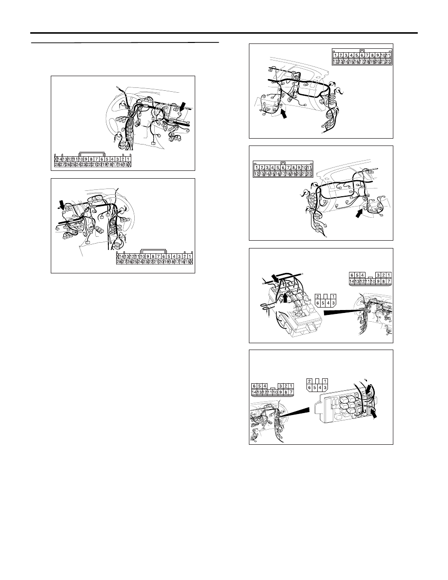
STEP 10. Check the harness wire between 
ignition switch (ACC) and C-171 RV meter 
connector terminal No.11.

NOTE: 

Prior to the wiring harness inspection, check joint 
connector C-127, junction block connectors C-207 
and C-208, and repair if necessary.

• Check the IG (ACC) power supply open circuit 

and short circuit.

Q: Is the check result normal?

YES : 

Refer to ignition switch (

P.54A-22

).

NO : 

Retest the system.

AC903856

Connector: C-171 <LHD>

AY

Harness side

C-171 (GR)

AC903868

Connector: C-171 <RHD>

BQ

Harness side

C-171 (GR)

AC903853

Connector: C-127 <LHD>

AE

C-127 (GR)

AC903865

Connector: C-127 <RHD>

AD

C-127 (GR)

AC509934

Connectors: C-207, C-208 <LHD>

Junction block (Front view)

C-207

C-208

C-208

C-207

AB

Harness side

Harness side

AC509936

Connectors: C-207, C-208 <RHD>

C-207

C-208

C-207

Harness side

Harness side

C-208

AB

Junction block 
(Front view)

RV METER

CHASSIS ELECTRICAL

54A-472

STEP 11. Measure the voltage at C-171 RV meter 
connector. 

(1) Disconnect the connector, and measure at the 

wiring harness side.

(2) Ignition switch: ON position

(3) Measure the voltage between C-171 RV meter 

connector terminal No.26 and body earth

OK: System voltage

Q: Is the check result normal?

YES : 

Go to Step 1

NO : 

Go to Step 12 

AC903856

Connector: C-171 <LHD>

AY

Harness side

C-171 (GR)

AC903868

Connector: C-171 <RHD>

BQ

Harness side

C-171 (GR)

AC402679

Connector C-171 
(Harness side)

GY

RV METER

CHASSIS ELECTRICAL

54A-473

STEP 12. Check the harness wire between 
ignition switch (IG1) and C-171 RV meter 
connector terminal No.26.

NOTE: 

Prior to the wiring harness inspection, check joint 
connectors C-132, C-138 and C-137, junction block 
connectors C-207 and C-209, and repair if neces-
sary.

• Check the IG (IG1) power supply open circuit and 

short circuit.

Q: Is the check result normal?

YES : 

Refer to ignition switch (

P.54A-22

).

NO : 

Retest the system.

AC903856 AZ

Connectors: C-137, C-138, C-171 <LHD>

C-138 (L)

C-137, C-138

C-171

C-137 (L)

Harness side

C-171 (GR)

AC903868

Connectors: C-137, C-138, C-171 <RHD>

BS

C-138 (L)

C-137, C-138

C-137 (L)

Harness side

C-171

C-171 (GR)

AC903853

Connector: C-132 <LHD>

AC

C-132 (GR)

AC903865

Connector: C-132 <RHD>

AB

C-132 (GR)

AC509934 AS

Connectors: C-207, C-209 <LHD>

Harness side

C-209

C-207

Harness side

C-209

C-207

Junction block (Front view)

AC509936 AN

Connectors: C-207, C-209 <RHD>

Harness side

C-209

C-207

Harness side

C-209

C-207

Junction block (Front view)

RV METER

CHASSIS ELECTRICAL

54A-474

STEP 13. Replace the RV meter temporarily and 
retest the system.
Check that the RV meter shows the drive information 
when the RV meter is replaced temporarily. 

Q: Is the check result normal?

YES : 

Replace the RV meter.

NO : 

Go to Step 14 

STEP 14. Retest the system.
Check that the RV meter RV meter shows the drive 
information.

Q: Is the check result normal?

YES : 

The procedure is complete.

NO : 

Return to Step 1. 

Inspection Procedure 2: The drive information is not displayed normally.

CIRCUIT OPERATION
The RV meter calculates, from the calculation value 
of the following information, the drive information that 
consists of average fuel consumption, possible cruis-
ing distance, and average vehicle speed. If the func-
tion type is set as 2 or 4 by mistake, the RV meter 
does not communicate with the engine-ECU. Also, 
the RV meter does not display the drive information.

• The vehicle speed signal is calculated from the 

vehicle speed pulse received from the vehicle 
speed sensor.

• The remaining fuel amount is calculated from the 

data received from the fuel gauge unit.

• The fuel injection quantity is calculated from the 

fuel injection quantity data received from the 
engine-ECU by CAN communication.

COMMENTS ON TROUBLE SYMPTOM
CAN bus line, harness between RV meter and fuel 
gauge unit, harness between RV meter and fuel 
gauge unit, RV meter, engine-ECU, vehicle speed 
sensor, or fuel gauge unit may be faulty.

PROBABLE CAUSES

• Malfunction of the CAN bus line

• Malfunction of the RV meter

• Malfunction of the Engine- ECU

• Malfunction of the fuel gauge unit

RV Meter Drive Information Circuit

RV METER

FUEL 
GAUGE 
UNIT

Wire colour code 
B : Black     LG : Light green     G : Green     L : Blue     W : White     Y : Yellow     SB : Sky blue 
BR : Brown     O : Orange     GR : Grey     R : Red     P : Pink     V : Violet     PU : Purple     SI : Silver

ENGINE 
CONTROL 
RELAY

VEHICLE 
SPEED 
SENSOR


Content   ..  774  775  776  777   ..