Mitsubishi L200. Manual - part 766


  Index      Mitsubishi     Mitsubishi L200 - service repair manual 2012 year


Search            


Content   ..  764  765  766  767   ..


Mitsubishi L200. Manual - part 766


HANDS FREE-ECU

CHASSIS ELECTRICAL

54A-431

INSTALLATION SERVICE POINT

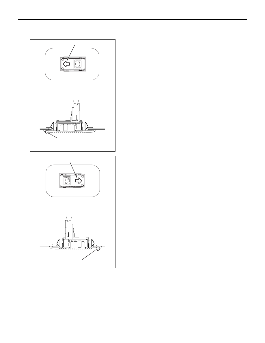
>>A<< MICROPHONE UNIT INSTALLATION

Install the microphone unit so that the arrow and 
direction mark face toward the driver's seat.

ACB01738

Direction mark

Direction mark

AB

<LHD>

AC903585

Direction mark

Direction mark

AD

<RHD>

USB BOX

CHASSIS ELECTRICAL

54A-432

REMOVAL AND INSTALLATION

M1546024200290

USB BOX

SPECIAL TOOLS

M1549100300028

AC802108

1

2.5 ± 0.5 N·m

2

AB

Removal Steps 

1.

Steering wheel voice control switch 
cover

2.

Steering wheel voice control switch

Tool

Number

Name

Use

MB991223

a. MB991219
b. MB991220
c. MB991221
d. MB991222

Harness set

a. Check 

harness

b. LED harness
c. LED harness 

adapter

d. Probe

Continuity check and voltage 
measurement at harness wire or 
connector

a. For checking connector pin 

contact pressure

b. For checking power supply 

circuit

c. For checking power supply 

circuit

d. For connecting a locally sourced 

tester

MB992006

Extra fine probe

Continuity check and voltage 
measurement at harness wire or 
connector

MB991223

a

d

c

b

DO NOT USE

BA

MB992006

USB BOX

CHASSIS ELECTRICAL

54A-433

TROUBLESHOOTING

STANDARD FLOW OF DIAGNOSTIC TROUBLESHOOTING

M1549100400207

Refer to GROUP 00 

− Troubleshooting contents .

DIAGNOSIS MODE <USING RADIO AND CD PLAYER>

M1549101600293

Enter the diagnosis mode according to the following 
steps:
1. Turn the Ignition switch to the "ACC" or "ON" 

position and switch off the radio and CD player.

2. Press the following buttons in that order within 

sixty seconds from step (1).
(1)  [CH1] button.
(2) TUNE/SEEK (Down-step/Down-seek) button.
(3) TUNE/SEEK (Up-step/Up-seek) button.
(4) [CH4] button.

NOTE: When the "Power" button of the radio and CD 
player is pressed during the diagnosis mode, the 
diagnosis mode will be cancelled, thus switching off 
the radio and CD player.
3. "USB - BOX DIAG" is displayed.

ACB02015

AC

Power

[CH1]

[CH4]

[CH3]

[CH2]

[CH6]

[CH5]

TUNE/SEEK 
(Up-step/Up-seek)

Return

TUNE/SEEK 
(Down-step/Down-seek) 

Select

Mode change

USB BOX

CHASSIS ELECTRICAL

54A-434

DIAGNOSIS MODE <USING MULTIVISION DISPLAY>

M1549101600301

HOW TO INITIATE THE SERVICE MODE
Refer to MMCS - Service mode 

P.54A-305

.

HOW TO TERMINATE THE SERVICE MODE
Refer to MMCS - Service mode 

P.54A-305

.

1. Select "USB BOX" on "Service" screen.

2. Displays the version information of the USB box.

NOTE: 

.

H/W version: The hardware version informa-
tion of the USB box is displayed in 2 digits.

S/W version: The software version information 
of the USB box is displayed in 7 digits.

AC905418

USB - BOX DIAG

H/W Ver.

S/W Ver.

CH4

CH4

CH3

CH3

AD

Radio and CD player OFF

CH4

CH1

TUNE/SEEK (Up-step/Up-seek)

TUNE/SEEK 

(Down-step/Down-seek)

Description in the 
illustrations

Actual display

Condition

USB - BOX DIAG

USB - BOX DIAG

Displayed when the diagnosis mode is being entered.

H/W Ver.

H/W XX

Two-digit hardware version is displayed.

S/W Ver.

S/W XXXXXXX

Seven-digit software version is displayed.

ACB01773

Service

Vehicle Signal Check

Monitor Check

Camera Setting

Speaker Check

Network/Connect Line Check

Car Type Setting

Versions Indication

1/2

Sensor Check

USB BOX

Handle Setting

Back

Next

Previous

USB BOX

H/W version

S/W version

XX

XX. YY.  ZZZ

AC904707

AB


Content   ..  764  765  766  767   ..