Mitsubishi L200. Manual - part 739


  Index      Mitsubishi     Mitsubishi L200 - service repair manual 2012 year


Search            


Content   ..  737  738  739  740   ..


Mitsubishi L200. Manual - part 739


MITSUBISHI MULTI COMMUNICATION SYSTEM (MMCS)

CHASSIS ELECTRICAL

54A-323

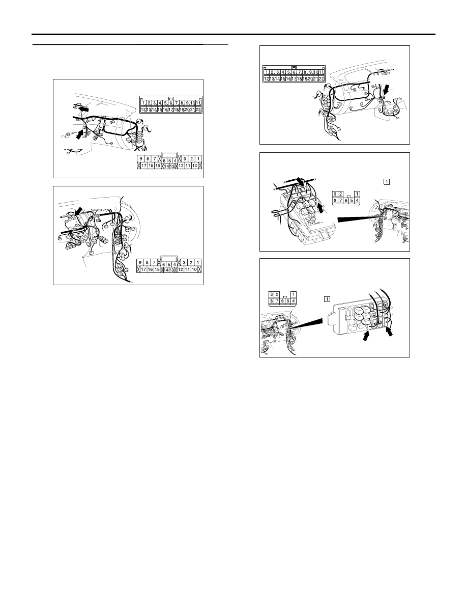
STEP 11. Check the wiring harness between C-
170 multivision display connector terminal No.17 
and fusible link (20).

• Check the power supply lines (battery supply) for 

open circuit  and short circuit.

NOTE: 

Prior to the wiring harness inspection, check junction 
block connectors C-213, C-209 and joint connector 
C-132, and repair if necessary.

Q: Is the check result normal?

YES : 

Troubleshoot the ignition switch. Refer to 

P.54A-22

.

NO : 

Repair the wiring harness.

AC903853

Connectors: C-132, C-170 <LHD>

AY

C-132 (GR)

C-132

C-170 (GR)

Harness side

C-170

AC903868

BF

Connector: C-170 <RHD>

C-170 (GR)

Harness side

AC903865

Connector: C-132 <RHD>

AB

C-132 (GR)

AC509934

Connectors: C-209, C-213 <LHD>

Junction block (Front view)

C-213

C-209

C-213

C-209

AC

Harness side

Harness side

AC509936

Connectors: C-209, C-213 <RHD>

C-213

C-209

AC

Junction block 
(Front view)

C-213

C-209

Harness side Harness side

MITSUBISHI MULTI COMMUNICATION SYSTEM (MMCS)

CHASSIS ELECTRICAL

54A-324

STEP 12. Voltage measurement at C-169 
multivision display connector.

(1)  Disconnect C-169 multivision display connector, 

and measure at the wiring harness-side 
connector.

(2) Voltage between C-169 multivision display 

terminal No.21 and the body earth

OK: System voltage

Q: Is the check result normal?

YES : 

Go to Step 14.

NO : 

Go to Step 13.

AC903853

C-169 (GR)

Harness side

AW

Connector: C-169 <LHD>

AC903868

C-169 (GR)

Harness side

BH

Connector: C-169 <RHD>

AC310507 LX

Connector C-169 
(Harness side)

MITSUBISHI MULTI COMMUNICATION SYSTEM (MMCS)

CHASSIS ELECTRICAL

54A-325

STEP 13. Check the wiring harness between C-
169 multivision display connector terminal No.21 
and fusible link (20).

NOTE: 

Prior to the wiring harness inspection, check junction 
block connectors C-213, C-209 and joint connector 
C-132, and repair if necessary.

• Check the power supply lines (battery supply) for 

open circuit and short circuit.

Q: Is the check result normal?

YES : 

The trouble can be an intermittent 

malfunction (Refer to GROUP 00, How to 
use Troubleshooting/inspection Service 
Points, How to Cope with Intermittent 
Malfunction ).

NO : 

Repair the wiring harness.

STEP 14. Retest the system
Check if the multivision display power is turned ON.

Q: Is the check result normal?

AC903853

Connectors: C-132, C-169 <LHD>

AZ

C-132 (GR)

C-169 (GR)

Harness side

C-132

C-169

AC903868

C-169 (GR)

Harness side

BH

Connector: C-169 <RHD>

AC903865

Connector: C-132 <RHD>

AB

C-132 (GR)

AC509934

Connectors: C-209, C-213 <LHD>

Junction block (Front view)

C-213

C-209

C-213

C-209

AC

Harness side

Harness side

AC509936

Connectors: C-209, C-213 <RHD>

C-213

C-209

AC

Junction block 
(Front view)

C-213

C-209

Harness side Harness side

MITSUBISHI MULTI COMMUNICATION SYSTEM (MMCS)

CHASSIS ELECTRICAL

54A-326

YES : 

The trouble can be an intermittent 

malfunction (Refer to GROUP 00 

− How to 

use Troubleshooting/inspection Service 
Points 

− How to Cope with Intermittent 

Malfunction ).

NO : 

Replace the multivision display.


Content   ..  737  738  739  740   ..