Mitsubishi L200. Manual - part 684


  Index      Mitsubishi     Mitsubishi L200 - service repair manual 2012 year


Search            


Content   ..  682  683  684  685   ..


Mitsubishi L200. Manual - part 684


HEADLAMP

CHASSIS ELECTRICAL

54A-103

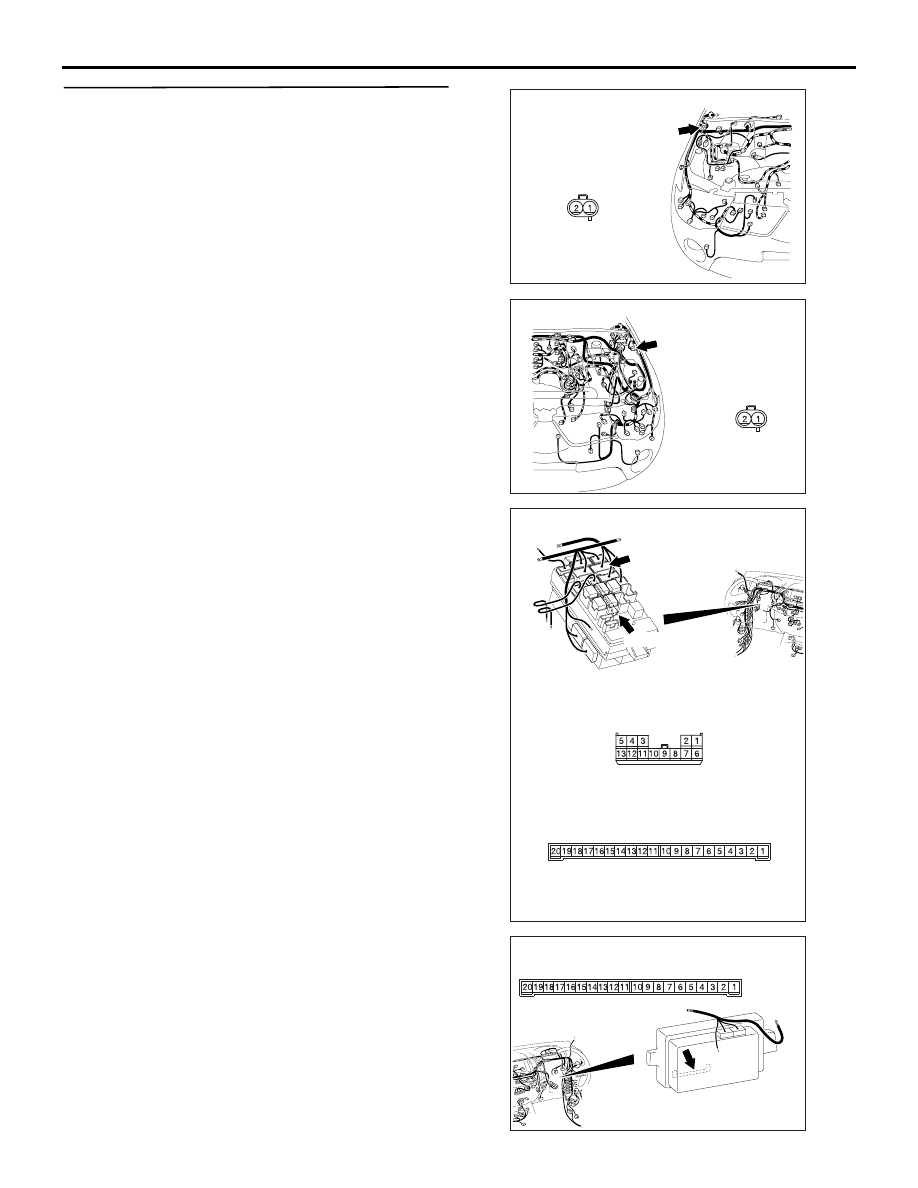
STEP 14. Check the wiring harness from the A-
114 side turn-signal lamp (LH) connector terminal 
No.2 or A-101 side turn-signal lamp (RH) 
connector terminal No.2 to C-218 ETACS-ECU 
connector terminal No.3 or No.4.

AC903897

AD

Harness side

A-101 (GR)

Connector: A-101

AC903898

AE

Harness side

A-114 (GR)

Connector: A-114

AC509935AL

Connectors: C-210, C-218 <LHD>

C-210

Harness side

C-210

C-218

Junction block side

C-218

AC509943

Connector: C-218 <RHD>

AC

Junction block

 (Rear view)

Junction block side

HEADLAMP

CHASSIS ELECTRICAL

54A-104

NOTE: 

Prior to the wiring harness inspection, check junction 
block connector C-210, and repair if necessary.

• Check the output lines for open circuit.

Q: Is the check result normal?

YES : 

Go to Step 15.

NO : 

Repair the wiring harness. Go to Step 23.

STEP 15. Retest the system.
Check that the side turn-signal lamps illuminate nor-
mally.

Q: Is the check result normal?

YES : 

The trouble can be an intermittent 

malfunction (Refer to GROUP 00 

− How to 

use Troubleshooting/inspection Service 
Points 

− How to Cope with Intermittent 

Malfunction ). Go to Step 23.

NO : 

Replace the side turn-signal lamp. Go to 
Step 23.

STEP 16. Connector check: F-04 <vehicles with 
rear body> or F-23 <vehicles without rear body> 
rear combination lamp (turn: LH) or F-02 
<vehicles with rear body> or F-19 <vehicles 
without rear body> rear combination lamp (turn: 
RH).

Q: Is the check result normal?

YES : 

Go to Step 17.

NO : 

Repair the defective connector. Go to Step 
23.

STEP 17. Check the bulb(s) of rear turn-signal 
lamps.
Check the bulb(s) of the defective lamp.

Q: Is the check result normal?

YES : 

Go to Step 18.

NO : 

Replace the bulb(s) of the defective lamp. 
Go to Step 23.

STEP 18. Resistance measurement at the  F-04 
<vehicles with rear body> or F-23 <vehicles 
without rear body> rear combination lamp (turn: 
LH) or F-02 <vehicles with rear body> or F-19 
<vehicles without rear body> rear combination 
lamp (turn: RH) connector.

(1) Disconnect the connector, and measure at the 

wiring harness side.

(2) Resistance measurement between the defective 

AC509936

Connector: C-210 <RHD>

Harness side

BD

Junction block 

(Front view)

AC903957AC

Harness side

F-02 (B)

Connectors: F-02, F-04, F-19, F-23

<Vehicles without 
rear body>

F-19

F-23

F-02, F-04

F-04 (B)

Harness side

F-19, F-23

AC903957AC

Harness side

F-02 (B)

Connectors: F-02, F-04, F-19, F-23

<Vehicles without 
rear body>

F-19

F-23

F-02, F-04

F-04 (B)

Harness side

F-19, F-23

HEADLAMP

CHASSIS ELECTRICAL

54A-105

lamp connector terminal and body earth.

Resistance between F-04 rear combination lamp 

(turn: LH) or F-02 rear combination lamp 
(turn: RH) connector terminal No.5 and body 
earth <vehicles with rear body>

Resistance between F-23 rear combination lamp 

(turn: LH) or F-19 rear combination lamp 
(turn: RH) connector terminal No.5 and body 
earth <vehicles without rear body>

OK: Continuity exists (2 

 or less)

Q: Is the check result normal?

YES : 

Go to Step 20.

NO : 

Go to Step 19.

STEP 19. Check the wiring harness from F-04 
<vehicles with rear body> or F-23 <vehicles 
without rear body> rear combination lamp (turn: 
LH) or F-02 <vehicles with rear body> or F-19 
<vehicles without rear body> rear combination 
lamp (turn: RH) connector terminal No.5 to body 
earth.

NOTE: Prior to the wiring harness inspection, check 
intermediate connector F-07, and repair if necessary.

• Check the earth wires for open circuit.

Q: Is the check result normal?

YES : 

The trouble can be an intermittent 

malfunction (Refer to GROUP 00 

− How to 

use Troubleshooting/inspection Service 
Points 

− How to Cope with Intermittent 

Malfunction ). Go to Step 23.

NO : 

Repair the wiring harness. Go to Step 23.

AC310506

Connectors F-02 , F-04

(Harness side)

FV

AC310506

Connectors F-19, F-23

(Harness side)

JN

AC903957AC

Harness side

F-02 (B)

Connectors: F-02, F-04, F-19, F-23

<Vehicles without 
rear body>

F-19

F-23

F-02, F-04

F-04 (B)

Harness side

F-19, F-23

HEADLAMP

CHASSIS ELECTRICAL

54A-106

STEP 20. Connector check: C-218 ETACS-ECU 
connector

Q: Is the check result normal?

YES : 

Go to Step 21.

NO : 

Repair the defective connector. Go to Step 
23.

AC509934

Connector: C-218 <LHD>

AJ

Junction 

block

Junction block side

AC509943

Connector: C-218 <RHD>

AC

Junction block

 (Rear view)

Junction block side


Content   ..  682  683  684  685   ..