Mitsubishi L200. Manual - part 680


  Index      Mitsubishi     Mitsubishi L200 - service repair manual 2012 year


Search            


Content   ..  678  679  680  681   ..


Mitsubishi L200. Manual - part 680


COMBINATION METER

CHASSIS ELECTRICAL

54A-87

ON-VEHICLE SERVICE

CHECK THE SPEEDOMETER

M1540201400608

CAUTION

Since the diagnosis code may be stored in the 
ABS-ECU or ASTC-ECU when checking the 
speedometer with speedometer tester, erase the 
diagnosis code.

CAUTION

Do not accelerate or decelerate suddenly during 
servicing work.
1. Check that the current tyre inflation pressures 

meet the inflation pressure label (Refer to 
GROUP 31 

− On-vehicle Service ).

2. Move <4WD> transfer shift lever to "4H" position.

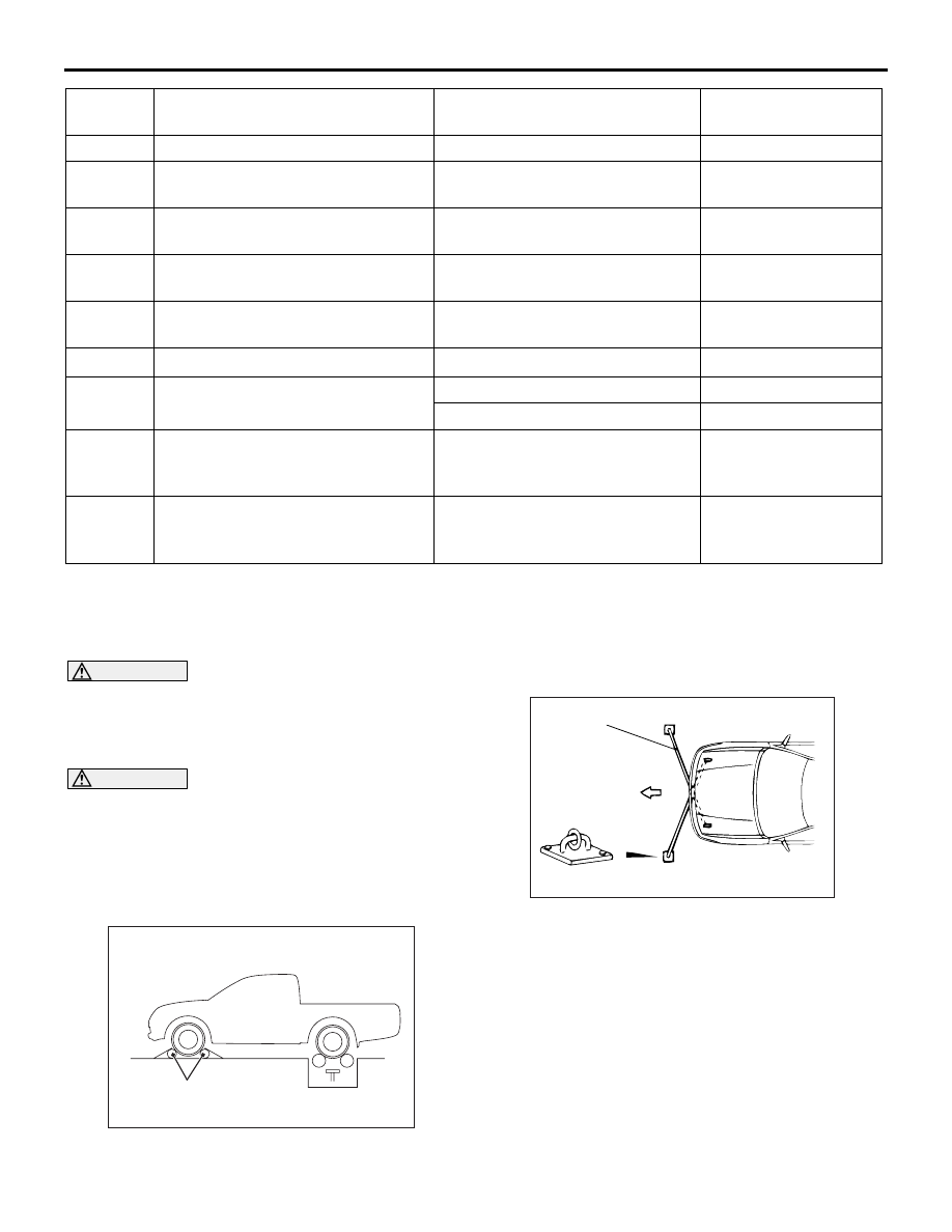
3. Set the vehicle on the speedometer tester and set 

the front wheels on the free roller.

4. For prevention of front wheel lateral runout, install 

chain or wire (the other end of which is tightly 
fixed on front towing hooks) on the vehicle.

5. For prevention of rear wheel lateral runout and of 

vehicle from starting out, install extension fittings 
on rear towing hooks, and install both ends in the 
anchor plate.

6. Check that the speedometer indicating range is 

within the standard value and the needle 
fluctuation is within the limit.

Standard value <Speedometer to display km/
h only>:

15

Illumination (earth)

Always

1 V or less

16

Illumination (power supply)

Illumination switch: ON and 
lighting switch: ON

System voltage

17

Brake warning lamp

Ignition switch: ON and brake 
warning lamp: ON

System voltage

18

SRS air bag warning lamp

Ignition switch: ON and SRS air 
bag warning lamp: ON

System voltage

19

ABS warning lamp

Ignition switch: ON and ABS 
warning lamp: ON

System voltage

20, 21

22

Input of fuel gauge

Fuel: FULL

Approximately 2 V

Fuel: EMPTY

Approximately 8 V

23

Input of turn-signal lamp RH switch Ignition switch: ON and turn-

signal lamp (RH) switch: ON and 
turn-signal lamp: ON (turn: ON)

System voltage

24

Input of high beam switch

Ignition switch: ON and high 
beam switch: ON and high beam 
indicator: ON (beam: ON)

System voltage

Terminal 
No.

Check items

Check conditions

Normal conditions

AC802659AB

Free roller

AC001288

Tension bar

Front

Anchor plate

AB

COMBINATION METER

CHASSIS ELECTRICAL

54A-88

Standard value <Speedometer to display 
MPH and km/h>:

Limit: Needle fluctuation (Vehicle speed is 35 
km/h or more) 

± 3 km/h

TACHOMETER CHECK

M1540201500036

1. Connect the engine speedometer to the fuel 

injection pipe.

2. Compare the readings of the engine speedometer 

and the tachometer at every engine speed, and 
check if the variation are within the standard 
value.

Standard value:

NOTE: The value in parentheses is a reference 
value.

FUEL GAUGE UNIT CHECK

M1540201600657

NOMINAL RESISTANCE OF THE FUEL GAUGE 
UNIT
1. Remove the fuel gauge unit (Refer to GROUP 

13B, Fuel Tank ).

2. When float of the fuel gauge unit is in stopper 

positions "F" and "E", ensure that resistance 
between the fuel gauge unit terminal and earth 
terminal is within the standard value.

Standard value:

3. When the float is moved slowly between stopper 

positions "F" and "E", ensure that the resistance is 
smoothly changing.

FUEL GAUGE UNIT FLOAT HEIGHT
1. Remove the fuel gauge unit (Refer to GROUP 

13B, Fuel Tank ).

Speed km/h

Speedometer 
indicating tolerance 
km/h

20

20.0 

− 24.0

40

40.0 

− 44.0

80

80.5 

− 85.5

120

121.5 

− 127.5

160

162.5 

− 169.5

Speed km/h 
(mph)

Speedometer indicating 
tolerance km/h (mph)

20 (10)

20.0 

− 24.0 (10.0 − 12.5)

40 (25)

40.0 

− 44.0 (25.0 − 27.5)

80 (50)

80.5 

− 85.5 (50.3 − 53.5)

120 (75)

121.5 

− 127.5 (76.0 − 80.0)

160 (100)

162.5 

− 169.5 (101.5 − 106.0)

Engine speed r/min

Tachometer indicating 
tolerance r/min

700

700 

± 100

(2,000)

(2,000 

± 100)

3,000

3,000 

± 150

(4,000)

(4,000 

± 200)

5,000

5,000 

± 250

AC503029

Engine
speedometer

Fuel injection pipe

AC

Float position

Gauge resistance 

Stopper position "F"

13.0 

± 1

Stopper position "E"

120.0 

± 1

AC503942AB

Fuel gauge unit

Earth

 Position "E"

Position "F"

COMBINATION METER

CHASSIS ELECTRICAL

54A-89

2. When float is moved to contact the float arm on 

the stopper, ensure that stopper positions "F" and 
"E" are within the standard value.

Standard value:

ENGINE COOLANT TEMPERATURE 
GAUGE UNIT CHECK

M1540207200022

1. Bleed the engine coolant.(Refer to GROUP 14 

− 

On-vehicle Service .)

2. Remove the engine coolant temperature gauge 

unit.

3. Immerse the unit in 50

°C water to measure the 

resistance.

Standard value: 239 

Reference value

4. After inspection, apply specified sealant at 

threads of water temperature gauge unit, and 
tighten to the specified torque.

Semi-drying sealant: 3M ATD Part No.8660 or 
equivalent

5. Add engine coolant.(Refer to GROUP 14 

− On-

vehicle Service .)

Float position

Float height mm

Stopper position "F"

35.0 

± 3

Stopper position "E"

254.7 

± 3

AC503030AB

 Position "E"

Position "F"

A

B

ACX00779 AI

Circuit tester

Thermometer

Temperature (

°C)

Resistance 

83

70.2

105

34.9

122

21.5

ACX00780AH

11 ± 1 N·m

COMBINATION METER

CHASSIS ELECTRICAL

54A-90

REMOVAL AND INSTALLATION

M1540201700030

INSTALLATION SERVICE POINT

>>A<< COMBINATION METER INSTALLATION

Fixing order of screws from 1 to 3.

AC805299

2

1

AB

Removal steps 

1.

Combination meter bezel (Refer 
to GROUP 52A, Instrument Panel 
Assembly ).

>>

A

<<

2.

Combination meter assembly

AC509356

1

2

3

AB


Content   ..  678  679  680  681   ..