Mitsubishi L200. Manual - part 665


  Index      Mitsubishi     Mitsubishi L200 - service repair manual 2012 year


Search            


Content   ..  663  664  665  666   ..


Mitsubishi L200. Manual - part 665


IMMOBILIZER SYSTEM

CHASSIS ELECTRICAL

54A-27

IMMOBILIZER SYSTEM

GENERAL INFORMATION

M1541107100076

The engine immobilizer system prevents the engine 
from starting and immobilizes the vehicle if a key 
other than the key registered for that vehicle is used 
in an attempt to start the engine after forced entry. 
The engine immobilizer system consists of the igni-
tion key, key ring antenna, ETACS-ECU (immobi-
lizer-ECU) and the engine-ECU. It works in the 
following way and has these functions.

1. With the ignition key turned ON, the transponder 

(a small transmitter) integrated in the ignition key 
transmits its own key ID to the key ring antenna 
via radio wave. 

2. According to the sent key ID, the ETACS-ECU 

(immobilizer-ECU) controls the engine-ECU only 
when the sent key ID agrees with the pre-regis-
tered one.

3. The system is designed to be maintenance-free 

because the power source for the transponder is 
supplied by the ETACS-ECU (immobilizer-ECU). 
Two ignition keys are provided, and up to eight 
keys can be registered to one vehicle as needed. 
More than one trillion of key ID combinations can 
be registered, and parts of them are irregularly 
changed whenever the ignition key is turned ON. 
This feature prevents code copying, resulting in 
higher security of the system.

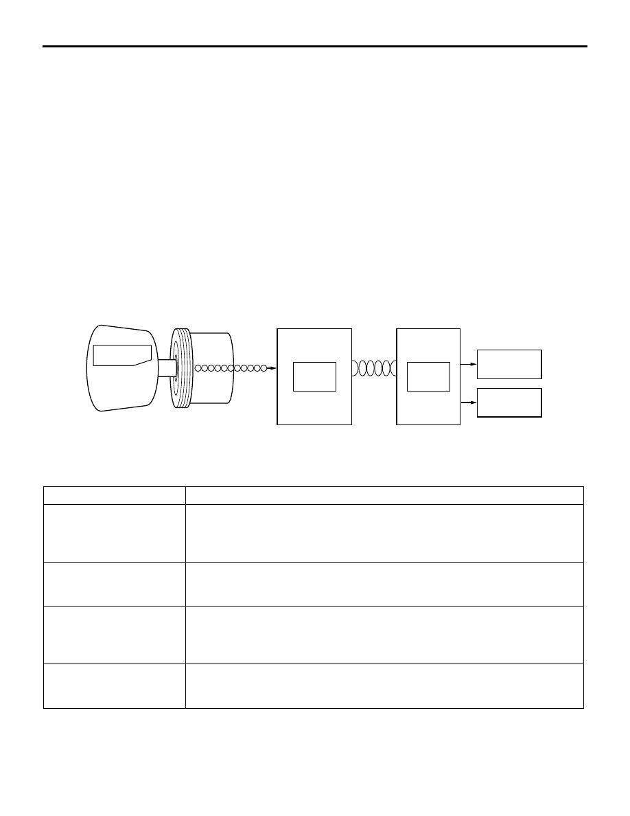
CONSTRUCTION DIAGRAM

MAIN COMPONENTS

AC406526

AQ

CPU

CPU

Ignition key

CAN

Key ID

Transponder

Steering lock

Injector

Key ring antenna

ETACS-ECU
(Immobilizer-ECU)

Engine-ECU

Ignition

Component name 

Outline of function

Transponder

Is power-supplied by the key ring antenna. When the transponder receives 
random number data, the transponder processes random number data and the 
key ID. Then it transmits the process result to the ETACS-ECU (immobilizer-
ECU).

Key ring antenna

The ETACS-ECU (immobilizer-ECU) supplies power via an antenna on a 
steering lock by transmission of electromagnetic waves to a transponder built 
into a key, using magnetic coupling

ETACS-ECU (immobilizer-
ECU)

• Supplies electrical power to the transponder integrated in the ignition key, 

and transmits random number data.

• Verifies the key ID which is sent from the transponder. If the code is correct, 

it sends an engine mobilization signal to the engine-ECU. 

Engine-ECU

Starts the engine, and then continues the engine running if an engine 
mobilization signal is confirmed. If an engine immobilization signal is 
confirmed, the ECU cancels the engine control and stops the engine.

IMMOBILIZER SYSTEM

CHASSIS ELECTRICAL

54A-28

SPECIAL TOOLS

M1541106600090

IMMOBILIZER SYSTEM

CHASSIS ELECTRICAL

54A-29

Tool

Number

Name

Use

MB991955

a. MB991824
b. MB991827
c. MB991910
d. MB991911
e. MB991825
f. MB991826

M.U.T.-III sub-
assembly

a. Vehicle 

Communication 
Interface (V.C.I.)

b. M.U.T.-III USB 

cable

c. M.U.T.-III main 

harness A 
(Vehicles with 
CAN 
communication 
system)

d. M.U.T.-III main 

harness B 
(Vehicles without 
CAN 
communication 
system)

e. M.U.T.-III 

measure adapter

f. M.U.T.-III trigger 

harness

CAUTION

For vehicles with CAN 
communication, use M.U.T.-
III main harness A to send 
simulated vehicle speed. If 
you connect M.U.T.-III main 
harness B instead, the CAN 
communication does not 
function correctly.
Diagnosis code check

MB991223

a. MB991219
b. MB991220
c. MB991221
d. MB991222

Harness set

a. Check harness
b. LED harness
c. LED harness 

adapter

d. Probe

Continuity check and voltage 
measurement at harness wire 
or connector

a. For checking connector pin 

contact pressure

b. For checking power supply 

circuit

c. For checking power supply 

circuit

d. For connecting a locally 

sourced tester

MB991910

MB991826

MB991955

MB991911

MB991824

MB991827

MB991825

a

b

c

d

e

f

DO NOT USE

MB991223

a

d

c

b

DO NOT USE

BA

IMMOBILIZER SYSTEM

CHASSIS ELECTRICAL

54A-30

TROUBLESHOOTING

DIAGNOSIS TROUBLESHOOTING FLOW

M1541106700020

Refer to GROUP 00 

− Contents of Troubleshooting .

DIAGNOSTIC FUNCTION

M1541100500170

HOW TO READ DIAGNOSIS CODE

Refer to GROUP 00, How to Use Troubleshooting/
Inspection Service Points .

HOW TO ERASE DIAGNOSIS CODE

Refer to GROUP 00, How to Use Troubleshooting/
Inspection Service Points . 

CHECK OF FREEZE FRAME DATA

The freeze frame data can be checked by using 
M.U.T.-III. (Refer to GROUP 00 

− How to Use Trou-

bleshooting and Inspection Service Points 

− Diagno-

sis Function .
When detecting fault and storing the diagnosis code, 
the ECU connected to CAN bus line obtains the data 
before the determination of the diagnosis code and 
the data when the diagnosis code is determined, and 
then stores the ECU status of that time. By analysing 
each data from M.U.T.-III, the troubleshooting can be 
performed more efficiently. The displayed items are 
as the table below.

Display item list

CHART CLASSIFIED BY DIAGNOSIS 
CODES

M1541100400173

CAUTION

During diagnosis, a diagnosis code associated 
with other system may be set when the ignition 
switch is turned on with connector(s) discon-
nected. On completion, confirm all systems for 
diagnosis code(s). If diagnosis code(s) are set, 
erase them all.

MB992006

Extra fine probe

Continuity check and voltage 
measurement at harness wire 
or connector

Tool

Number

Name

Use

MB992006

Item No.

Item name

Data item

Unit

2

Ignition cycle

Number of times the ignition switch is turned 
"ON" or "LOCK (OFF)" after the past failure 
transition.

Number of 
counts is 
displayed.

3

Elapsed time

Total elapsed time after a diagnosis code is 
generated

min

4

Accumulated minute

Cumulative time for current malfunction of 
diagnosis code

min

Code No.

Diagnosis contents

Reference page

B1702

Reception error of key ID

P.54A-31

B1703

Key ID inconsistent

P.54A-32

B1722

Transponder antenna failure

P.54A-32

B1731

Communication error with the engine-ECU

P.54A-35


Content   ..  663  664  665  666   ..