Mitsubishi L200. Manual - part 650


  Index      Mitsubishi     Mitsubishi L200 - service repair manual 2012 year


Search            


Content   ..  648  649  650  651   ..


Mitsubishi L200. Manual - part 650


DRIVER'S AND PASSENGER'S (FRONT) AIR BAG MODULE(S) AND CLOCK SPRING

SUPPLEMENTAL RESTRAINT SYSTEM (SRS)

52B-271

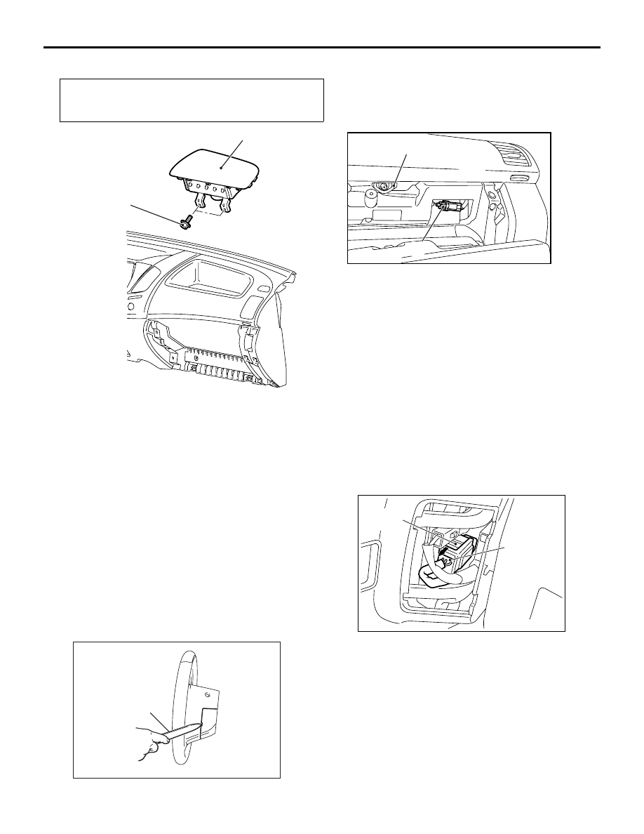
<PASSENGER'S (FRONT) AIR BAG MODULE>

Pre-removal Operation
• Turn the ignition switch to the "LOCK" (OFF) position.
• Disconnect the Negative Battery Terminal.

AC801610

Glove box striker

2

1

AB

5.0 ± 1.0 N·m

Removal steps 

<<

F

>>

1. Passenger’s (front) air bag module 

connector connection

Glove box cover (Refer to GROUP 
52A, Instrument panel assembly ).

<<

G

>>

2. Passenger’s (front) air bag module

Installation steps 

>>

A

<< • Pre-installation inspection

2. Passenger’s (front) air bag module

Glove box cover (Refer to GROUP 
52A, Instrument panel assembly ).

1. Passenger’s (front) air bag module 

connector connection

Negative battery cable connection

>>

D

<< • Post-installation inspection

REMOVAL SERVICE POINTS

<<A>> COVER REMOVAL

AC211761AB

MB990784

Insert the special tool ornament remover 
(MB990784) as shown in the illustration to remove 
the cover.

<<B>> DRIVER’S AIR BAG MODULE 
CONNECTOR DISCONNECTION

AC501669

AC

Locking 
button

Clock spring 
connector

Disconnect the clock spring connector while com-
pressing its locking button and sliding it to the direc-
tion of an arrow.

DRIVER'S AND PASSENGER'S (FRONT) AIR BAG MODULE(S) AND CLOCK SPRING

SUPPLEMENTAL RESTRAINT SYSTEM (SRS)

52B-272

<<C>> DRIVER’S AIR BAG MODULE REMOVAL

WARNING

The air bag module must not be measured 
with such equipment as an ohmmeter, nor 
disassembled.

AC501231

Mounting screw 

(Torx screw)

AB

The removed air bag module should be 
stored in a clean, dry place with the 
deployment surface facing up.

1. Remove the bag module mounting screws (Torx 

screws) at the sides of the steering wheel.
NOTE: Do not remove the screws from the hold-
ers.

<<D>> STEERING WHEEL REMOVAL
1. Position the steering wheel in the straight-ahead 

position.

AC000991

MB990803

AD

2. Use special tool steering wheel puller 

(MB990803) to remove the steering wheel.

<<E>> CLOCK SPRING REMOVAL

WARNING

The removed clock spring should be stored 
in a clean, dry place.

<<F>> PASSENGER’S (FRONT) AIR BAG 
MODULE CONNECTOR DISCONNECTION

AC701980

Glove box 
striker

AC

Passenger's (front) 
air bag module 
harness side connector

Lock lever

Pull up the passenger’s (front) air bag module har-
ness side lock lever with a mail and disconnect the 
connector lock.

<<G>> PASSENGER’S (FRONT) AIR BAG 
MODULE REMOVAL

WARNING

When the passenger’s (front) air bag mod-
ule is removed, do not damage the 
engagement of the pawls.

The removed passenger’s (front) air bag 
module should be stored in a clean, dry 
place with facing the deployment surface 
facing up.

INSTALLATION SERVICE POINTS

>>A<< PRE-INSTALLATION INSPECTION

WARNING

Dispose of air bag modules only according 
to the specified procedure (Refer to 

P.52B-

289

).

1. When installing the new air bag modules and 

clock spring, refer to “INSPECTION” (

P.52B-274

).

2. Connect the negative battery cable.

AC509179

AB

Diagnosis

connector

MB991827

MB991824 

MB991910

<LH drive vehicles>

DRIVER'S AND PASSENGER'S (FRONT) AIR BAG MODULE(S) AND CLOCK SPRING

SUPPLEMENTAL RESTRAINT SYSTEM (SRS)

52B-273

CAUTION

To prevent damage to M.U.T.-III, always turn the 
ignition switch to the “LOCK” (OFF) position 
before connecting or disconnecting M.U.T.-III.
3. Connect M.U.T.-III to the diagnosis connector.
4. Turn the ignition switch to the “ON” position.
5. Check diagnosis codes using M.U.T.-III to ensure 

that the SRS operates properly.
At this time, check that no diagnosis code except 
B1400 and B1410 are set.

6. Turn the ignition switch to the "LOCK" (OFF) 

position. Disconnect the negative battery cable 
and tape the terminal to prevent accidental 
connection and air bags deployment.

>>B<< CLOCK SPRING INSTALLATION

WARNING

Ensure that the clock spring’s mating marks 
are properly aligned. If not, the steering 
wheel may not rotate completely during a 
turn, or the flat cable in the clock spring 
could be damaged, This would prevent nor-
mal SRS operation and possibly cause seri-
ous injury to the driver.

AC705283 AC

Mark for 
checking 
neutral point 

Mating marks

Align the mating marks of the clock spring.
<Alignment of mating marks>
1. Turn the clock spring clockwise fully.
2. Turn the clock spring anti-clockwise 

approximately three and 1/2 turns to align the 
mating marks.

3. Check that the white or yellow roller can be seen 

from the window for checking the neutral point 
when the mating marks are aligned.
NOTE: If the white or yellow roller cannot be seen 
or black roller can be seen, the neutral point is not 
aligned correctly.

4. Turn the front wheels to the straight-ahead 

position. Then install the clock spring to the 
column switch.

>>C<< STEERING WHEEL/DRIVER’S AIR BAG 
MODULE INSTALLATION

CAUTION

When installing the steering wheel, and driver’s 
air bag module ensure that the harness of the 
clock spring does not become caught or tangled.
1. Before installing the steering wheel, and driver’s 

air bag module turn the vehicle’s front wheels to 
the straight-ahead position and align the mating 
marks of the clock spring.

2. After securing the steering wheel, turn the 

steering wheel all the way in both directions to 
confirm that the steering wheel rotation is normal.

DRIVER'S AND PASSENGER'S (FRONT) AIR BAG MODULE(S) AND CLOCK SPRING

SUPPLEMENTAL RESTRAINT SYSTEM (SRS)

52B-274

>>D<< POST-INSTALLATION INSPECTION
1. Connect the negative battery cable.
2. Turn the ignition switch to “ON” position.

AC900540 AB

SRS warning lamp

3. Does the "SRS" warning lamp illuminate for 

approximately seven seconds, and go out?

4. If no, refer to troubleshooting (Refer to 

P.52B-12

).

INSPECTION

M1524014600619

AIR BAG MODULE CHECK

WARNING

If any component damage is found during 
the following inspection, replace the air 
bag module(s) with a new one. Dispose of 
the old one according to the specified 
procedure (Refer to 

P.52B-289

).

AC809499

Connector

Inflator case

Connector

Inflator case

Connector

Driver's air bag module

Passenger's (front) air bag module

<Vehicles without wide fender (optional)>

Connector

Inflator case

AC

<Vehicles with wide fender (optional)>

Never attempt to measure the circuit 
resistance of the air bag module (squib) 
even if you are using the specified tester. 
If the circuit resistance is measured with a 
tester, accidental air bag module(s) 
deployment will result in serious personal 
injury.

1. Check the pad cover for dents, cracks or 

deformation.

2. Check the connectors for damage, the terminals 

for deformation, and the harness for binds.


Content   ..  648  649  650  651   ..