Mitsubishi L200. Manual - part 590


  Index      Mitsubishi     Mitsubishi L200 - service repair manual 2012 year


Search            


Content   ..  588  589  590  591   ..


Mitsubishi L200. Manual - part 590


TROUBLESHOOTING

SUPPLEMENTAL RESTRAINT SYSTEM (SRS)

52B-31

Code No.B1403: Driver's air bag module (squib) system (short-circuited to the power supply)

AC806117

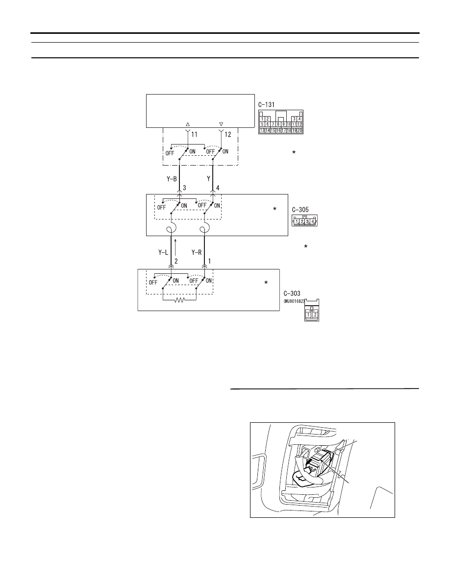
Driver's Air Bag Module (Squib) Circuit

AIR BAG MODULE
(SQUIB)
(DRIVER'S SIDE)

CONNECTOR
LOCK SWITCH

CONNECTOR
LOCK SWITCH

CLOCK SPRING

SRS-ECU

CONNECTOR
LOCK SWITCH

NOTE

: CONNECTOR COUPLED: ON 
  CONNECTOR UNCOUPLED: OFF

Wire colour code
B : Black     LG : Light green     G : Green     L : Blue     W : White     Y : Yellow     SB : Sky blue
BR : Brown     O : Orange     GR : Grey     R : Red     P : Pink     V : Violet     PU : Purple

AB

OPERATION

• The SRS-ECU judges how severe a collision is 

by detecting signals from the front impact sensors 
and the front air bag analogue G-sensor. If the 
impact is over a predetermined level, the SRS-
ECU sends an ignition signal. At this time, if the 
front air bag safing G-sensor is on, the SRS air 
bag will inflate. 

• The ignition signal is input to the air bag module 

via the clock spring to inflate the air bag.

DIAGNOSIS CODE SET CONDITIONS
This diagnosis code is set if the driver’s air bag squib 
wire(s) are short-circuited to the power supply.

PROBABLE CAUSES

• Malfunction of the clock spring

• Damaged harness wires and connectors

• Short to the power supply in the driver's air bag 

module (squib) harness

• Malfunction of the SRS-ECU

DIAGNOSIS PROCEDURE

STEP 1. Check the diagnosis code by connecting 
a dummy resistor. (M.U.T.-III diagnosis code)
(1) Disconnect the negative battery terminal.

AC501669

A

C-303 Air bag 
module connector

AB

(2) By sliding the A section (in the figure) of air bag 

module connector C-303 in arrow direction, 

TROUBLESHOOTING

SUPPLEMENTAL RESTRAINT SYSTEM (SRS)

52B-32

disconnect the connector.

AC303006AF

C-303 Air bag

module

connector

MB991865

(Dummy 

resistor : 3   )

MB991866 
(Resistor harness)

(3) Connect special tool dummy resistor (MB991865) 

to special tool resistor harness (MB991866).

CAUTION

Do not insert a test probe into the terminal from 
its front side directly as the connector contact 
pressure may be weakened.
(4) Insert special tool (MB991866) into clock spring 

side air bag module connector C-303 by 
backprobing.

(5) Connect the negative battery terminal.
(6) Erase the diagnosis code memory, and check the 

diagnosis code.

Q:  Is diagnosis code B1403 out put?

YES : 

Go to Step 2.

NO : 

Replace the driver’s air bag module (Refer 
to 

P.52B-268

). 

STEP 2. Check the diagnosis code by connecting 
a dummy resistor. (M.U.T.-III diagnosis code)
(1) Disconnect the negative battery terminal.

AC903858AD

Connector: C-305 <LHD>

Harness side 
connector 
(front view)

C-305 (Y)

AC903869AD

Connector: C-305 <RHD>

Harness side 
connector 
(front view)

C-305 (Y)

C-305

(2) Disconnect the clock spring connector C-305.

AC303587AN

C-305 Clock spring 

connector

MB991865
(Dummy resistor: 3    )

MB991866 

(Resistor harness)

(Rear view)

(3) Connect special tool dummy resistor (MB991865) 

to special tool resistor harness (MB991866).

CAUTION

Do not insert a test probe into the terminal from 
its front side directly as the connector contact 
pressure may be weakened.
(4) Insert special tool (MB991866) into clock spring 

harness side connector C-305 (terminal No.3 and 
4) by backprobing.

(5) Connect the negative battery terminal.
(6) Erase the diagnosis code memory, and check the 

diagnosis code.

Q:  Is diagnosis code B1403 set?

YES : 

Go to Step 3.

NO : 

Replace the clock spring (Refer to 

P.52B-

268

). 

TROUBLESHOOTING

SUPPLEMENTAL RESTRAINT SYSTEM (SRS)

52B-33

STEP 3. Voltage measurement at the SRS-ECU 
connector C-131.
(1) Disconnect the negative battery terminal.

AC501670

AB

C-131 (Y)

Connector: C-131

Harness side 
connector 
(rear view)

(2) Disconnect SRS-ECU connector C-131.

AC903858AD

Connector: C-305 <LHD>

Harness side 
connector 
(front view)

C-305 (Y)

AC903869AD

Connector: C-305 <RHD>

Harness side 
connector 
(front view)

C-305 (Y)

C-305

DANGER

To prevents the air bag from deploying unin-
tentionally, disconnect the clock spring con-
nector C-305 to short the squib circuit.

(3) Disconnect the clock spring connector C-305.

AC100391

Section
A - A

C-131 Harness side connectors
(front view)

Cable tie

Short spring

4 mm or more

Terminal

A

BE

A

CAUTION

Insert an insulator such as a cable tie to a depth 
of 4 mm or more, otherwise the short spring will 
not be released.
(4) Insert a cable tie [3 mm wide, 0.5 mm thick] 

between terminals 11, 12 and the short spring to 
release the short spring.

(5) Connect the negative battery terminal.
(6) Turn the ignition switch to the "ON" position.

AC006255

13 14 15 16 17 18 19 20

5 6 7 8 9 10 11 12

1 2

3 4

AX

C-131 Harness side 
connector (rear view)
 

CAUTION

Do not insert a test probe into the terminal from 
its front side directly as the connector contact 
pressure may be weakened.
(7) Voltage measurement between C-131 harness 

side connector terminals 11, 12 and body earth.

OK: 1 V or less

Q: Is the check result normal?

YES : 

Go to Step 4.

NO : 

Repair the harness wires between SRS-
ECU connector C-131 (terminal No.11 and 
12) and clock spring connector C-305 
(terminal No.3 and 4). 

STEP 4. Check whether the diagnosis code is 
reset.

Q: Is diagnosis code B1403 set?

TROUBLESHOOTING

SUPPLEMENTAL RESTRAINT SYSTEM (SRS)

52B-34

YES : 

Replace the SRS-ECU (Refer to 

P.52B-

266

).

NO : 

An intermittent malfunction is suspected 
(Refer to GROUP 00, How to Cope with 
Intermittent Malfunction ). 

Code No.B1404: Driver's air bag module (squib ignition drive circuit) system detected short circuit


Code No.B1405: Driver's air bag module (squib ignition drive circuit) system detected open circuit


Code No.B1414: Passenger’s (front) air bag module (squib ignition drive circuit) system detected 
short circuit


Code No.B1415: Passenger’s (front) air bag module (squib ignition drive circuit) system detected 
open circuit


Code No.B1466: Analogue G-sensor system in the SRS-ECU


Code No.B1467: Safing G-sensor open circuit


Code No.B1468: Safing G-sensor short circuit


Code No.B1478: SRS-ECU capacitor circuit voltage too high


Code No.B1479: SRS-ECU capacitor circuit voltage too low


Code No.B1496: SRS-ECU non-volatile memory (EEPROM)


Code No.B1497: SRS-ECU application specific integrated circuit  (for frontal activation)


Code No.B1498: SRS-ECU ROM or RAM


Code No.B1499: Collision decision


Code No.B1550: SRS warning lamp drive circuit malfunction


Code No.B1557: SRS-ECU application specific integrated circuit


Code No.B1607: Seat belt pre-tensioner (driver's side) (squib ignition drive circuit) system detected 
short circuit


Code No.B1608: Seat belt pre-tensioner (driver's side) (squib ignition drive circuit) system detected 
open circuit


Code No.B1613: Seat belt pre-tensioner (passenger’s side) (squib ignition drive circuit) system 
detected short circuit


Code No.B1614: Seat belt pre-tensioner (passenger’s side) (squib ignition drive circuit) system 
detected open circuit


DIAGNOSIS CODE SET CONDITIONS
These diagnosis code are set when a fault is 
detected in the SRS-ECU. The most likely causes for 
this code to be set are shown in the table below:

Code No.

Part/Circuit integral to SRS-
ECU

Trouble causes

B1404

Driver's air bag module (squib 
ignition drive circuit)

• Short circuit in the squib ignition drive circuit

B1405

• Open circuit in the squib ignition drive circuit

B1414

Passenger's (front) air bag 
module (squib ignition drive 
circuit)

• Short circuit in the squib ignition drive circuit

B1415

• Open circuit in the squib ignition drive circuit

B1466

Analogue G-sensor

• When the analogue G-sensor is not operating

• When the characteristics of the analogue G-sensor 

are abnormal

• When the output from the analogue G-sensor is 

abnormal


Content   ..  588  589  590  591   ..