Mitsubishi L200. Manual - part 578
TRIMS
INTERIOR
52A-18
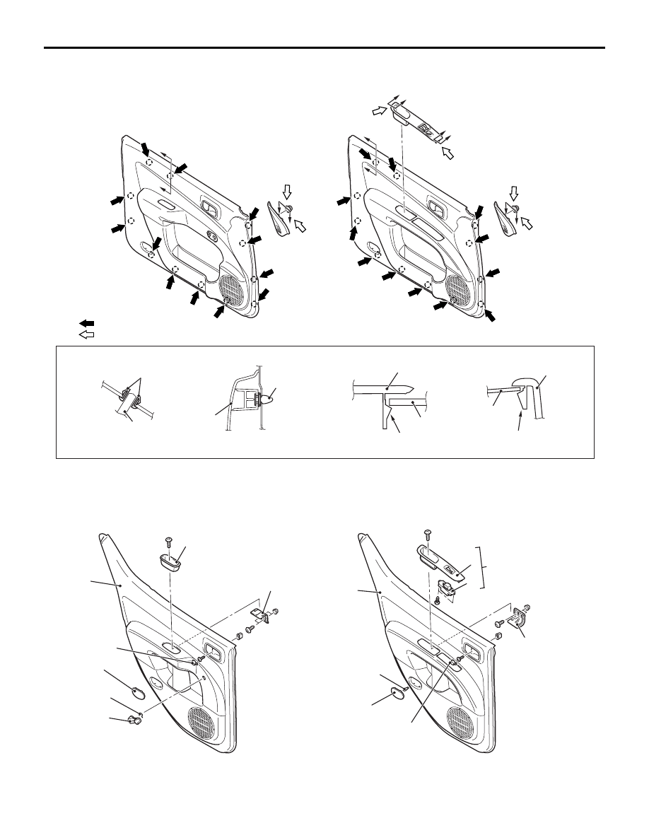
CLIP AND CLAW POSITIONS
AC509424AD
B
B
B
B
D
D
Clip
<Power window>
C
C
NOTE
(1) : Clip positions
(2) : Claw positions
Section B – B
Section C – C
Section D – D
Claw
<Manual window>
Section A – A
A
A
Claw
A
A
2
12
7
12
7
12
1
NOTE: Each number in the illustration indicates a
part number.
<REAR DOOR TRIM-DOUBLE CAB>
AC508266AB
6
5
11
1
7
10
4
8
<Power window>
<Manual window>
1
2
3
7
10
11
9