Mitsubishi L200. Manual - part 476
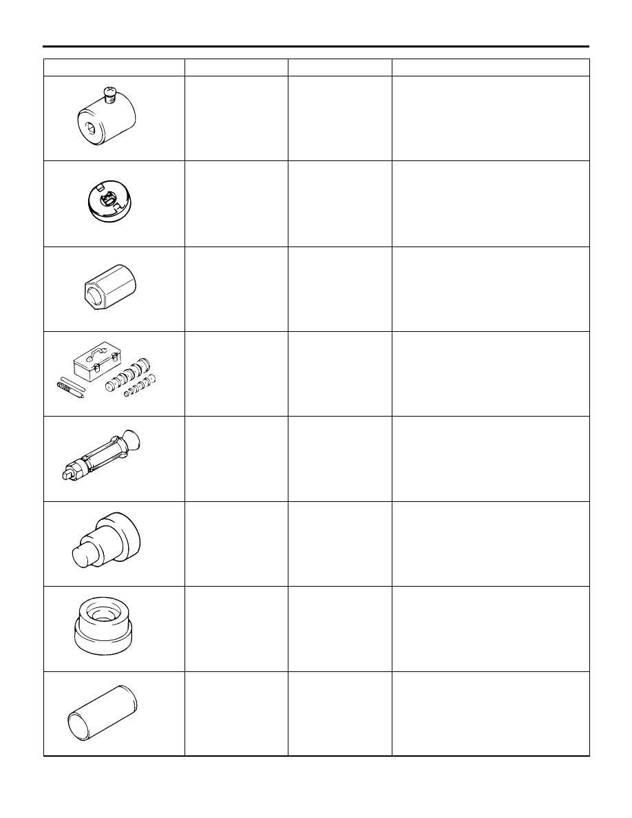
MB991006
SPECIAL TOOLS
POWER STEERING
37-7
MB991006
Preload socket
Steering gear total pinion torque
check and adjustment
MB991621
MB991621
Rack support cover
wrench
• Rack support cover removal <2WD
(except High rider)>
• Rack support adjustment <2WD
(except High rider)>
MB992351
MB992351
Torque wrench
socket
• Rack support cover removal <2WD
(High rider), 4WD>
• Rack support adjustment <2WD
(High rider), 4WD>
MB990925
MB990925
Bearing and oil
seal installer set
• Oil seal and bearing removal and
installation
• MB990927, MB990938, MB990939
(For details, refer to GROUP 26,
Special Tools .)
MB991120
MB991120
Needle bearing
puller
Needle roller bearing removal
MB991202
MB991202
Oil seal and
bearing installer
• Needle bearing installation
• Lower bearing installation
MB991203
MB991203
Oil seal and
bearing installer
Oil seal and bearing installation
MB991317
MB991317
Seal ring installer
Seal ring installation
Tool
Number
Name
Use