Mitsubishi L200. Manual - part 452
TROUBLESHOOTING
ACTIVE STABILITY & TRACTION CONTROL SYSTEM (ASTC)
35C-64
(6) Turn the ignition switch to the "LOCK" (OFF)
position.
Q: Is code No.C1226, C1231, C1236, C1241, C1246,
C1251, C1256, C1261, C1300 or C1310 set?
YES :
Go to Step 1.
NO :
The procedure is complete.
Code No.C1266: Motor system
Code No.C1273: Motor relay (stuck off)
Code No.C1274: Motor relay (stuck on)
Code No.C1280: Motor fail-safe relay (short circuit)
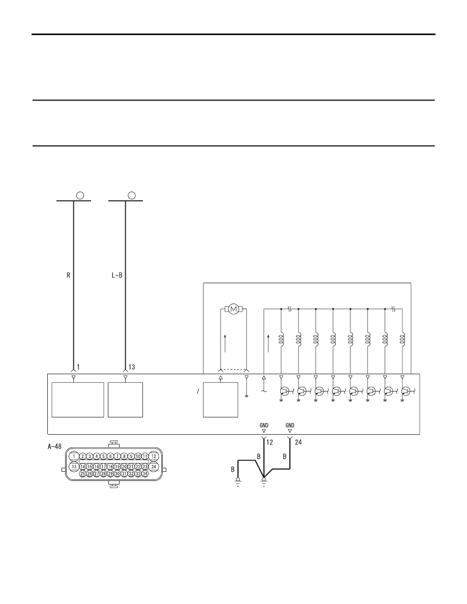
Solenoid Valve and Motor Power Supply Circuit
MOTOR
POWER
SOURCE
MOTOR
POWER
SOURCE
SOLENOID
VALVE
POWER
SOURCE
FUSIBLE
LINK
22
FUSIBLE
LINK
21
MOTOR SOLENOID
VALVE
HYDRAULIC UNIT
ASTC-ECU
Wire colour code
B : Black LG : Light green G : Green L : Blue W : White Y : Yellow SB : Sky blue
BR : Brown O : Orange GR : Grey R : Red P : Pink V : Violet PU : Purple
ACB00773