Mitsubishi L200. Manual - part 450
TROUBLESHOOTING
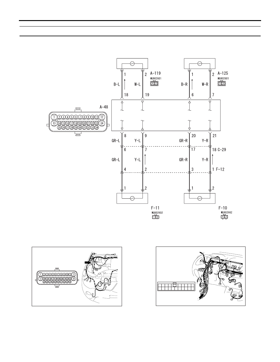
ACTIVE STABILITY & TRACTION CONTROL SYSTEM (ASTC)
35C-56
Code No.C1217: Wheel speed sensor (RL) (malfunction power circuit)
ACB00772
Wire colour code
B : Black LG : Light green G : Green L : Blue W : White Y : Yellow SB : Sky blue
BR : Brown O : Orange GR : Grey R : Red P : Pink V : Violet PU : Purple
Wheel Speed Sensor Circuit
ASTC-ECU
FRONT WHEEL
SPEED SENSOR
(LH)
FRONT WHEEL
SPEED SENSOR
(RH)
REAR WHEEL
SPEED SENSOR
(LH)
REAR WHEEL
SPEED SENSOR
(RH)
AC800980
AG
Connector: A-48
(B)
AC600687CB
Connectors: C-29 <LHD>
16
10
13
4
1112
1 2 3
15
14
5
20
18
17
19
7
6
8 9