Mitsubishi L200. Manual - part 424
TROUBLESHOOTING
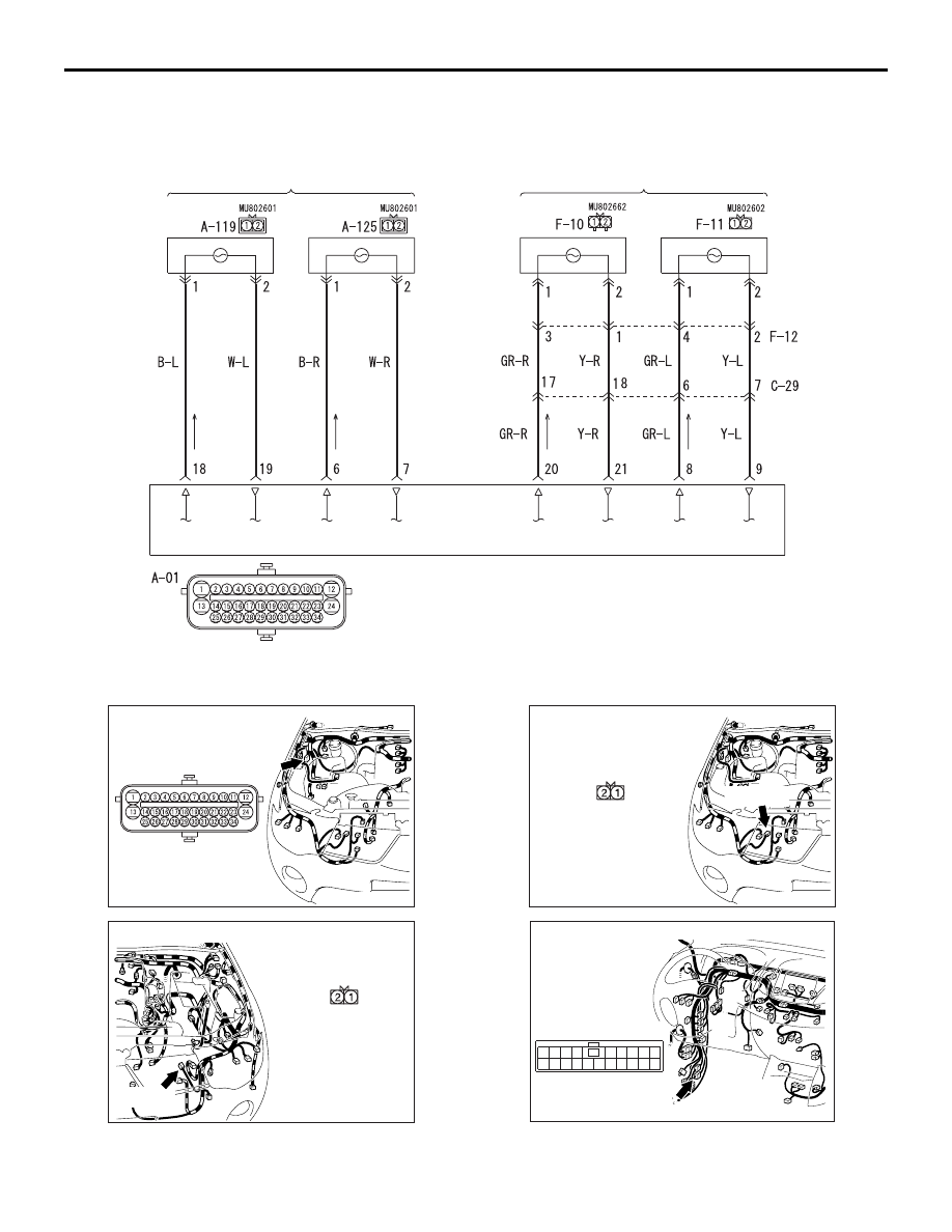
ANTI-SKID BRAKING SYSTEM (ABS)
35B-17
<2WD (High rider), 4WD>
Wire colour code
B : Black LG : Light green G : Green L : Blue W : White Y : Yellow SB : Sky blue
BR : Brown O : Orange GR : Grey R : Red P : Pink V : Violet PU : Purple
(LH)
(RH)
ABS-ECU
FRONT WHEEL SPEED SENSOR
REAR WHEEL SPEED SENSOR
Wheel Speed Sensor Circuit
(LH)
(RH)
ACB00767
AC501971
Connector: A-01
AU
(B)
AC502545AS
Connector: A-119
A-119 (B)
A-119 Harness
connector
(harness side)
AC501971AL
Connector: A-125
A-125 (B)
A-125 Harness
connector
(harness side)
AC600687CB
Connectors: C-29 <LHD>
16
10
13
4
1112
1 2 3
15
14
5
20
18
17
19
7
6
8 9