Mitsubishi L200. Manual - part 393


  Index      Mitsubishi     Mitsubishi L200 - service repair manual 2012 year


Search            


Content   ..  391  392  393  394   ..


Mitsubishi L200. Manual - part 393


REAR DIFFERENTIAL LOCK <4WD>

REAR AXLE

27-23

REAR DIFFERENTIAL LOCK AIR PUMP 
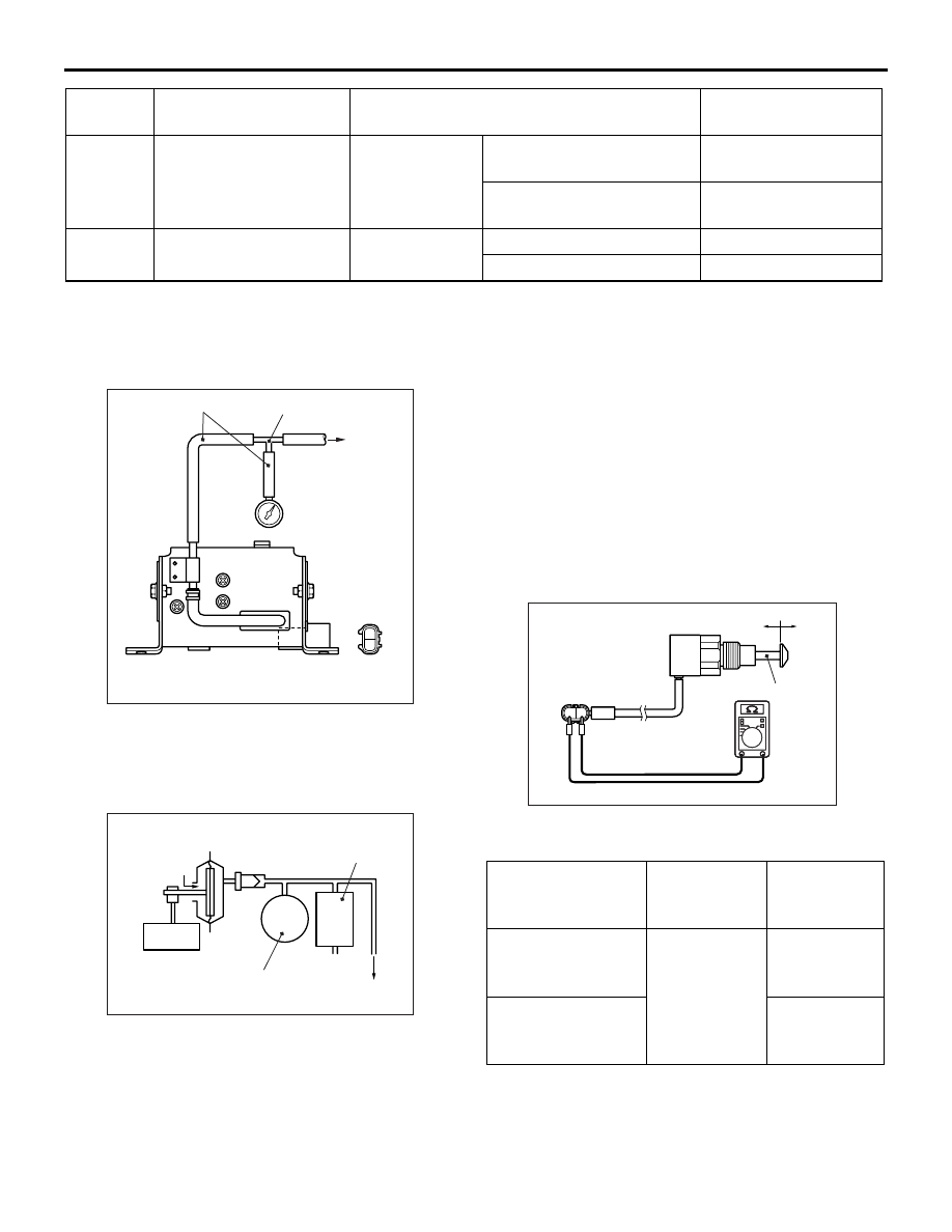
CHECK

M1272003100038

1. Install the air hose to the differential.

1

2

AC508812AB

Air hose

T-joint

Pressure 
gauge

Battery (-)

Battery (+)

Differential

2. Connect a pressure gauge to the air pump 

discharge outlet nozzle, via the air hose and T-
joint.

3. Apply battery voltage to the air pump connector.

AC508813AB

Differential

Release
valve

Pressure
switch

Motor

Atmosphere

4. Measure the time when the pump starts and stops 

operating, and if it stops within 5 seconds, the 
pressure switch inside the pump is normal.

5. Measure the pressure 10 

− 20 seconds after the 

pump has stopped.

Standard value: 24.5 

 39 kPa (-30  0°C), 

24.5 

 34 kPa (0  100°C)

6. If the pressure is within the standard value, the 

release valve inside the pump is normal.

7. Check the pump does not begin operating for 5 

minutes after it has stopped.

8. If the inspection for steps 4-7 is normal, the pump 

is fully operational.

REAR DIFFERENTIAL LOCK DETECTION 
SWITCH CHECK

M1272001000057

2

1

AC711365AB

Rod

ON

OFF

Check for continuity between the terminals of the 
switch.

Measurement 
condition

Terminal 
connector of 
tester

Specified 
condition

When the rod is 
pulled

1 - 2

Continuity 
(less than 2 
Ω)

When the rod is 
returned to its 
normal position

Open circuit

1

Rear differential lock 
switch (OFF position)

Ignition switch: 
ON

Rear differential lock switch 
is pushed.

1 V or less

Rear differential lock switch 
is not pushed.

System voltage 

10

Rear differential lock 
indicator lamp

Ignition switch: 
ON

Rear differential is locked

1 V or less

Rear differential is free

System voltage

Terminal 
No.

Item

Condition

Terminal voltage

DIFFERENTIAL CARRIER ASSEMBLY

REAR AXLE

27-24

DIFFERENTIAL CARRIER ASSEMBLY

REMOVAL AND INSTALLATION

M1272002000867

Pre-removal Operation
• Differential Gear Oil Draining
• Axle Shaft Assembly Removal (Refer to 

P.27-15

.) 

Post-installation Operation
• Axle Shaft Assembly Installation (Refer to 

P.27-15

.) 

• Differential Gear Oil Filling (Refer to 

P.27-9

.)

<2WD>

AC808347AD

50 ± 10 N·m

1

60 ± 10 N·m

27 ± 2 N·m*
47 ± 7 N·m*

54 ± 5 N·m
103 ± 5 N·m

3

2

4

5

6

N

N

Sealant: 
ThreeBond 1217 or equivalent

A

A

Section A-A

2.0 - 2.5 mm
2.5 - 3.0 mm

 : Except High rider
 : High rider

*

1

2

1

7

8

9

AC808355

 <Except High 
  rider>

 <High rider>

7

8

9

Sealant: 
ThreeBond 1217 or equivalent

NOTE:

2

2

*

1

*

2

*

1

*

Removal steps 

<<

A

>> >>

C

<< 1. Propeller shaft

2. Drain plug
3. Packing
4. Filler plug
5. Gasket

<<

B

>>

6. Differential carrier assembly
7. Vent plug <Except High rider>

>>A<<

8. Vent plug <High rider>

>>A<<

9. Plug cover <High rider>

Removal steps (Continued)

DIFFERENTIAL CARRIER ASSEMBLY

REAR AXLE

27-25

<4WD>

AC900084AD

1

60 ± 10 N·m

47 ± 7 N·m

103 ± 5 N·m

N

N

3

2

4

7

5

8

11 ± 2 N·m

50 ± 10 N·m

6

1

60 ± 10 N·m

47 ± 7 N·m

103 ± 5 N·m

N

N

3

2

4

7

5

8

9

22 ± 4 N·m

11 ± 2 N·m

10

<Vehicles with 
High power engine 
except 5A/T>

<5A/T or 
except vehicles with
High power engine>

9

50 ± 10 N·m

6

11

12

11

12

Sealant: 
ThreeBond 1217 or equivalent

A

A

Section A-A

2.5 - 3.0 mm

AC808355

11

12

Sealant: 
ThreeBond 1217 or equivalent

Breather
hose

<Vehicles with rear differential lock>

Removal steps 

<<

A

>> >>

C

<< 1. Propeller shaft

2. Rear differential lock detection switch 

connector connection <Vehicles with 
rear differential lock>

>>

B

<< 3. Vacuum hose connection <Vehicles 

with rear differential lock>

4. Drain plug
5. Packing
6. Filler plug
7. Gasket

<<

B

>>

8. Differential carrier assembly
9. Protector <Vehicles with rear 

differential lock>

10. Protector <Vehicles with rear 

differential lock>

>>A<<

11. Vent plug <Vehicles without rear 

differential lock>

>>A<<

12. Plug cover <Vehicles without rear 

differential lock>

REMOVAL SERVICE POINTS

<<A>> PROPELLER SHAFT REMOVAL

CAUTION

Suspend the propeller shaft from the body with 
wire, etc. to avoid spilling transmission fluid and 
to avoid injury from falling propeller shaft when 
not secured.

AC003833

Mating marks

AC

Make the mating marks on the flange yoke of the 
propeller shaft and the companion flange of the dif-
ferential carrier.

DIFFERENTIAL CARRIER ASSEMBLY

REAR AXLE

27-26

<<B>> DIFFERENTIAL CARRIER REMOVAL

CAUTION

Use care not to strike the companion flange.

AC502392

Remove the attaching nuts. Strike the lower part of 
differential carrier assembly with a piece of wood 
several times to loosen the assembly. Remove the 
assembly.

INSTALLATION SERVICE POINTS

>>A<< PLUG COVER/VENT PLUG INSTALLATION

AC808356AB

Drain
groove

Slit

Vent plug

Plug cover

1. Place the drain groove of vent plug towards 

vehicle wheel side and install it on the axle 
housing.

2. Place the plug cover slit towards the vehicle rear 

side and install it.

>>B<< VACUUM HOSE CONNECTION

AC508832AE

Vacuum
hose

<5A/T or except vehicles with
High power engine>

AC600925AE

Vacuum
hose

<Vehicles with 
High power
engine
except 5A/T>

Connect the vacuum hose so that the red mark is 
located upward.

>>C<< PROPELLER SHAFT INSTALLATION

AC003833

Mating marks

AC

Align the mating marks on the flange yoke and the 
companion flange to install the propeller shaft.


Content   ..  391  392  393  394   ..