Mitsubishi L200. Manual - part 364
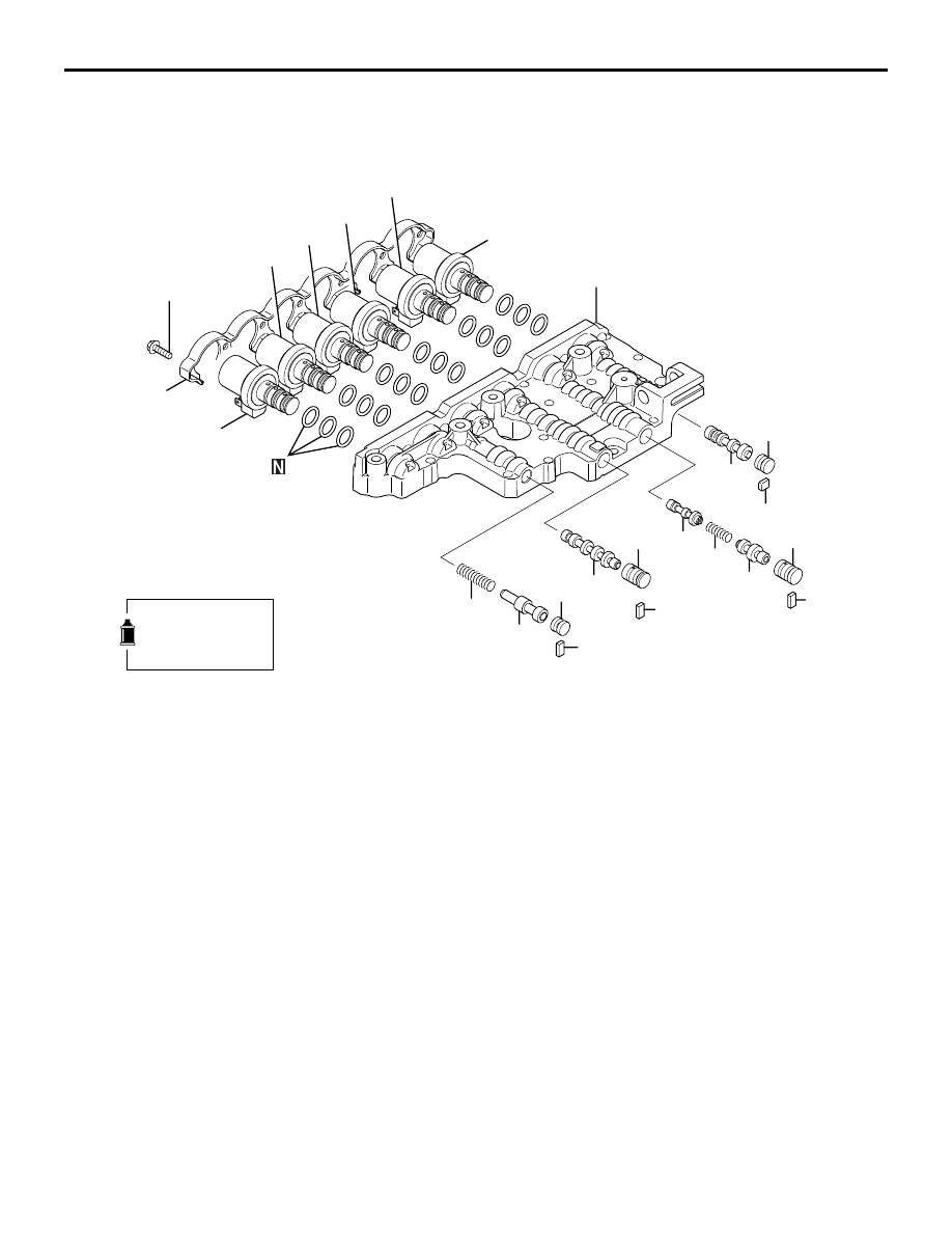
VALVE BODY
AUTOMATIC TRANSMISSION OVERHAUL <V5A5>
23D-71
>>C<<
14. Knock bushing
>>B<<
15. Dowel pin
AK602076
16
17
18
19
24
25
26
21
22
23
27
28
29
20
34
35
36
31
32
33
37
30
6.0 ± 1.0 N·m
38
AC
Apply automatic
transmission fluid
to all moving parts
before installation.
Disassembly steps
16. Solenoid support
<<A>>
>>A<<
17. Low/reverse brake solenoid valve
<<A>>
>>A<<
18. Reduction brake solenoid valve
<<A>>
>>A<<
19. Second brake solenoid valve
<<A>>
>>A<<
20. Underdrive clutch solenoid valve
<<A>>
>>A<<
21. Overdrive clutch solenoid valve
<<A>>
>>A<<
22. Damper clutch control solenoid
valve
23. Stopper plate
24. Stopper plug
25. Switching valve
26. Stopper plate
27. Fail-safe valve A sleeve
28. Fail-safe valve A2
29. Fail-safe valve A spring
30. Fail-safe valve A1
31. Stopper plate
32. Fail-safe valve B sleeve
33. Fail-safe valve B
34. Stopper plate
35. Stopper plug
36. Torque converter pressure control
valve
37. Torque converter pressure control
valve spring
38. Upper valve body
Disassembly steps (Continued)
Disassembly steps (Continued)