Mitsubishi L200. Manual - part 345
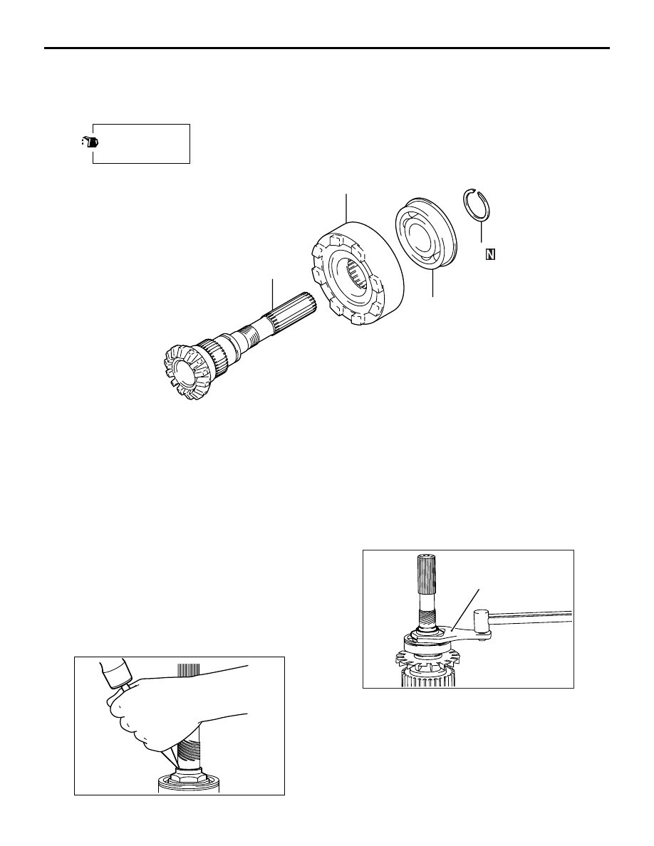
REAR OUTPUT SHAFT
AUTOMATIC TRANSMISSION OVERHAUL <V4A5>
23C-89
<Super select 4WD>
AK101106
1
2
3
4
AC
Apply gear oil to
all moving parts
before installation.
Disassembly steps
>>
B
<<
1.
Snap ring
<<
B
>>
>>
A
<<
2.
Ball bearing
3.
Viscous coupling
4.
Rear output shaft
DISASSEMBLY SERVICE POINTS
<<A>> LOCK NUT REMOVAL
AK403516
1. Remove the lock nut from the shaft.
AK500495
MB991013
AB
2. Hold the drive sprocket in a soft-jaw vise.
3. Shift the clutch sleeve to the drive sprocket side.
4. Use special tool Power steering lock nut special
spanner (MB991013) to remove the lock nut.