Mitsubishi L200. Manual - part 316
AKX00069
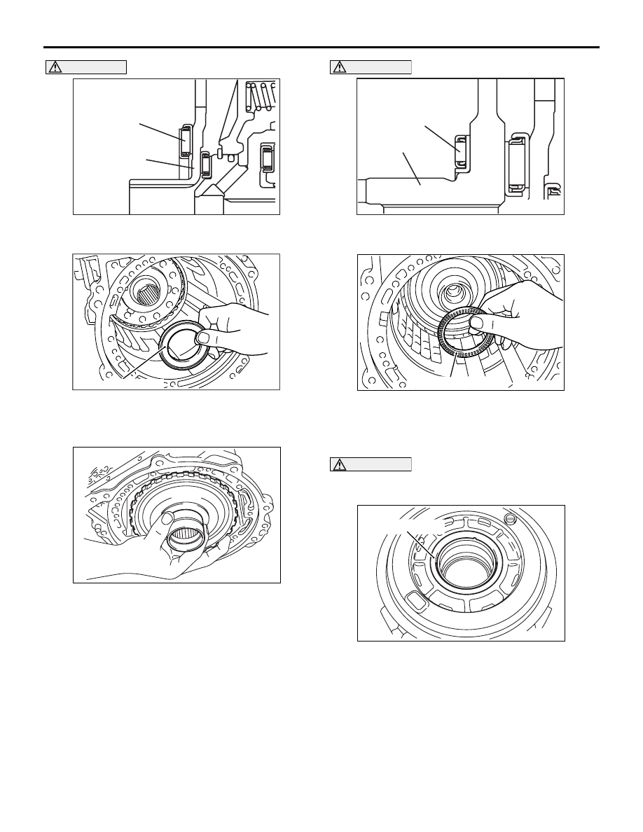
Thrust beaing No.10
Underdrive clutch
hub
AE
TRANSMISSION
AUTOMATIC TRANSMISSION OVERHAUL <R4A5>
23B-28
CAUTION
Make sure thrust bearing No.10 is mounted in the
correct direction.
AK403446
Thrust bearing
No.
10
AC
10.Apply vaseline or petroleum jelly on the thrust
bearing No.10, and then install it on the
underdrive clutch hub.
AK403447
11.Install the output flange.
AKX00072
Thrust bearing No.9
Output flange
AG
CAUTION
Make sure thrust bearing No.9 is mounted in the
correct direction.
AK403448
Thrust bearing No.9
AC
12.Apply vaseline or petroleum jelly on the thrust
bearing No.9, and then install on the output
flange.
CAUTION
Measure and record the thickness of the thrust
race No.8 to be assembled.
AK403449AD
Thrust race No.8
13.Apply vaseline or blue petroleum jelly on the
thrust race No.8 being used, and then install it on
the rear side of the center support.